Laying cables in pipes (part 2)
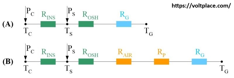
Figure (A) shows the thermal scheme of a cable line laid in the ground. The following designations are used: Pc, Ps – loss of active power in the core and metallic screen of the cable; Tc, Ts, Tg – temperature of the core, screen, ground; Rins, Rosh, Rg – thermal resistances of insulation, outer sheath, ground.
Figure (B) shows the thermal scheme of the cable laid in the ground in the pipe. Two additional elements appeared: Rair – the thermal resistance of the air in the pipe, taking into account its convection; Rp – the thermal resistance of the side wall of the pipe.
Comparing schemes (A) and (B), it is obvious that scheme (B) contains additional elements (air and pipe), that is, it seems that in scheme (B) it is more difficult for heat to get from the cable core into the surrounding ground. That is why people believe that in scheme (B) the temperature of the cable core will be higher than in scheme (A). Therefore, they believe that in scheme (B) it is necessary to take measures to reduce the heating of the core, that is, it is necessary to reduce the core current.
Hence, it turns out that in scheme (B) the long-term permissible current of the cable line is always less than in scheme (A). For example, it is generally assumed that when laying in pipes, the permissible current in the core of the cable line is 0.9 of the current characteristic when laying cables in the ground without pipes. In fact, this is not true.
The fallacy of the above reasoning is due to the fact that ground resistances Rg in schemes (A) and (B) are not equal to each other. As you know, thermal resistance is proportional to the area through which heat passes. So in scheme (A), heat goes into the ground through the side surface of the cable, whereas in scheme (B), heat goes into the ground through the side surface of the pipe. Since the diameter of the pipe is always several times larger than the diameter of the cable, the ratio RgA > RgB is valid.
So, in scheme (A), the chain of thermal resistances is shorter than in scheme (B), but in scheme (A), the thermal resistance of the soil Rg is several times greater than in scheme (B). Therefore, it is impossible to say in advance in which of the two schemes the conditions for cooling the cable will be better. The answer to this question can only be given by detailed calculations.
According to calculations, phase-by-phase laying of cables in pipes (compared to three phases in one pipe) can increase the surface of the system for so many times, that we get the unexpected result – the increase of permissible current of the line by 1.05-1.15 times. The specific value depends on the pipe diameter, the thermal resistance of the ground (depends on the depth of the laying).
The most significant increase in the permissible current is obtained if the single-core cables are laid in three pipes of large diameter and at a great depth, characteristic for the method of horizontal directional drilling.