
Connecting wire for cable termination
At the ends of the cable line, there are cable terminations. Metallic screens of cables are removed from terminations to the outside, where they are connected in accordance with selected bonding/ grounding scheme. For example, the figure shows the high voltage cable line with one-sided grounding of screens. To have this scheme, metallic screens, with the help of connecting wires (CW), pass from the cable termination to the box with surge arresters inside (these arresters are also known as cable outer Sheath Voltage Limiters, SVL). Unfortunately, sometimes in practice there are cases when CW is attached to the cable termination (or to its base plate) in not a proper way.
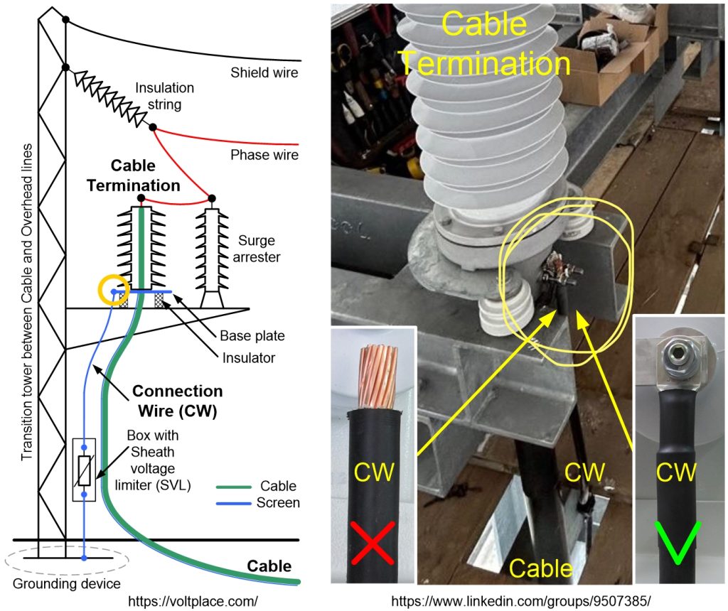
The photo shows the termination installed at the transition point between the cable and overhead line. Such termination was mounted at a height, and therefore we can see building structures and wood bridges that have not yet been removed. In the photo, you should pay attention to the node highlighted in yellow. It can be seen that the connecting wire CW is connected to the termination without any protection from environmental influences. In other words, there is no metallic tip and heat shrinkable tube on the CW.
The absence of a metallic tip and a heat shrinkable tube leaves opened the CW end, and water will enter the cable, which can lead:
1️⃣ To oxidation of copper.
2️⃣ To degradation of the insulation of the connecting wire (CW).
3️⃣ To degradation of places where CW is connected to the box (with or without a SVL inside).
Usually CW has a simple design – it is a core covered with insulation which also has purpose to behave as an outer sheath and protect CW from water penetration. In most cases we have copper core covered with a layer of insulation of several mm thick, which approximately corresponds to a voltage class about 6 kV (CW has the same insulation level as an outer sheath of the main high voltage cable). In other words, CW is not a 0.4 kV class wire. As well as SVL is not a 0.4 kV surge arrester.
In the photo shown, the CW insulation protects it well from water penetration in the radial direction. However, the lack of a tip and a heat shrinkable tube leads to the fact that the CW can collect a lot of water along its axis (from the top end downwards), and will not be able to withstand voltages arise on the core of CW. That’s why the tip and tube on it should be installed every time.