Selection of double-circuit cable line
The vast majority of cable lines (CL) are double-circuit. Two circuits are needed not only to increase the transmitted power, but also for reliability reasons. If one circuit turns out to be disconnected (for testing, damage locating, repair, replacement), then the second circuit can provide power supply to consumers (to load).
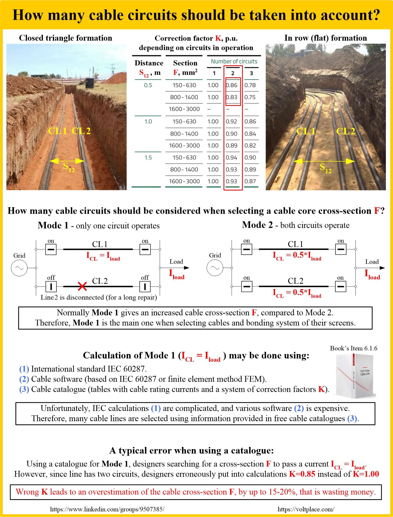
Two modes are possible when selecting cables of a double-circuit CL:
✅ Mode 1 – there is only one circuit in operation (say CL1), and it carries 100% of the total load capacity.
✅ Mode 2 – both circuits (CL1 and CL2) are in operation at once, and each carry only 50% of the total load capacity.
As a rule, mode 1 is the most severe. Therefore, mode 1 is used for selecting the cross-section of the cable core (taking into account the bonding system of cable screens). In this mode 1, the core of the cable should be selected based on the possibility of passing the 100% load current for a long time.

The selection of the core is carried out as a result of a thermal calculation which can be done in three different ways:
1️⃣ According to IEC 60287.
2️⃣ By cable software.
3️⃣ By using the results of the thermal calculation, which were already done by cable factories and provided in their cable catalogues.
Option (1) is quite complicated. Option (2) requires to buy software and have skills to work with it. Therefore, option (3) remains a common way to select the cable core cross-section, especially for 6-35 kV cables.
Option (3) is based on the fact that the catalogue has a table of cable line ratings for basic laying conditions (one circuit, 1.5 m depth, 20℃ temperature, no ducts, no power losses in cable screens, etc.), and many tables with correction factors (they are used if the actual laying conditions differ from the basic ones).
One of these tables is a table of correction factor K for the number of circuits (taking into account the distance s12 between the circuits which is normally about 0.5-0.7 m).
Although the cable core selection is carried out for the mode 1 (only one circuit remains in operation), designers often, seeing that the line is initially double-circuit, put into calculations not K=1.0, but the value K=0.85 valid for mode 2 only. Using K=0.85 instead of K=1.0 leads to an overestimation of the cable core cross-section, up to 15-20%, that is an increasing the cost of the cable and entire project.
Thus, if we use a system of correction factors for a double-circuit cable line, then there is no need to use the correction factor K=0.85 for a number of circuits. We should use K=1.0 despite the fact that our line is double-circuit.
Please read Item 6.1.6 of the book