Earth continuity conductor
Today we will not talk about alcohol (“bar”), but about a conductive element called:
✅ equipotential bar (bar, bus);
✅ earth continuity conductor (ECC).
Questions arise:
1️⃣ why do we need such a bar;
2️⃣ how to provide equal distances from the bar to all phases A,B,C;
3️⃣ how to calculate the optimal bar material and cross section (Fb).
Unfortunately, not all of these questions have clear answers in regulatory documents, and not every software gives the ability to account for such a bar. So let us discuss 1️⃣-2️⃣-3️⃣.
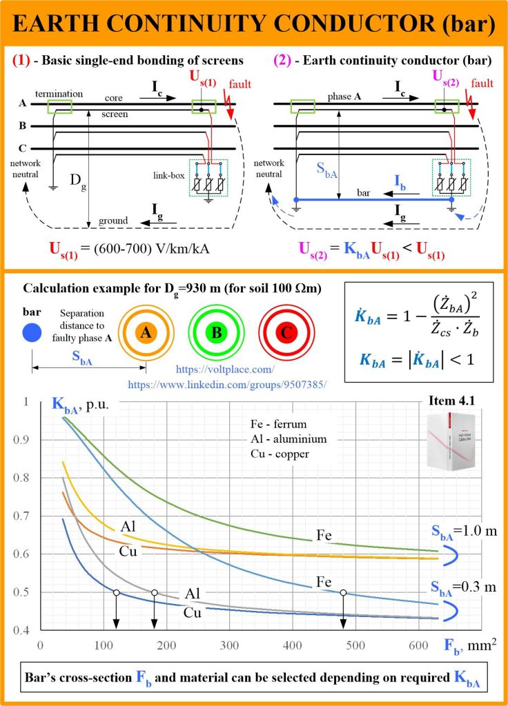
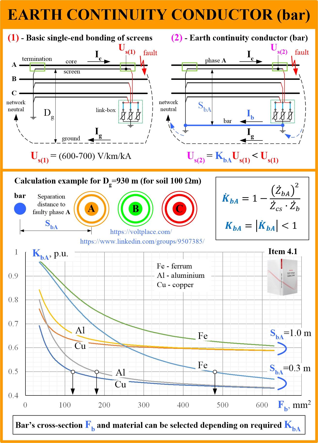
1️⃣ In network with solidly grounded neutral (110-500 kV), if the line length is less than 1 km, a typical solution is to use a single-end grounding of cable screens. In this situation, cable screens can have an AC 50 Hz induced voltage (Us) which can be dengerous especially in case of single-phase-to-ground short circuit (because magnetic field of the core current of the faulty phase A is not compensated by magnetic field of two unfaulty phases BC). To reduce Us, we can decrease the size of “screen-to-ground” contour which can be done by a grounded bar. This is a main reason to have a bar.
Sometimes, a bar may be used as a way to connect grounding systems at the ends of the cable line. It may be required when:
🔹 to decrease the grounding impedance of the transition tower by its connection to the grounding system of the switchgear (if an overhead line is connected to a switchgear by a cable insert);
🔹 to avoid stray (accidental) currents entering the cable screens from the ground (if screens are grounded at both sides of the cable line).
2️⃣ To make distances equal, there are several solutions:
🔹to change periodically the position of the bar relative to ABC cables;
🔹to have two bars located on different sides of ABC cables.
3️⃣ The algorithm is described in the book. The first thing to know is that a material of the bar and its cross-section have nothing to do with the material and cross-section of the cable screen. That is, if we have a 240 mm2 copper screen, then it does not mean that the bar should be like that. The bar is selected based on the calculation of the voltage induced to the screen. Algorithm is as follows:
🔹to calculate induced voltage (Us1) without a bar (by book or software);
🔹to compare (Us1) with permissible level Up (usually Us1>Up for any of 110-500 kV cable lines with a length of more than 500-600 m);
🔹to write simple equation Us2=K*Us1<Up and find a required effect that can be taken by the use of the bar – K<Up/Us1;
🔹to find the most optimal material and cross-section of the bar (Fb) which provides the required K.
For example, suppose we need to achieve K=0.5. Then, setting the distance from the bar to the faulty phase (let it be Sb=0.3 m), according to the graph taken from the book, we can have three different options:
✅ copper of 120 mm2 (looks like a “mini bar”);
✅ aluminium of 185 mm2;
✅ steel of 480 mm2 (looks like a “big bar”).
In the chapter 4.1 of the book, there is another calculation example made for Dg = 10 m (not for Dg = 930 m), and there is an explanation of why the author considers it as more reasonable. Please note, that the book contains not only the formula shown in the post (it was derived in the book), but also a formula that takes into account impedances of grounding systems at the ends of the line. These impedances decrease the effect of the bar.
The book “High Voltage Cable Lines” gives engineers simple, practical calculation methods that are often not found in standards and even in expensive software. You can purchase this book using the link https://voltplace.com/my-books/