
Features of HVDC cable projects
HVDC projects can be very roughly divided into two types:
1 – subsea;
2 – underground.
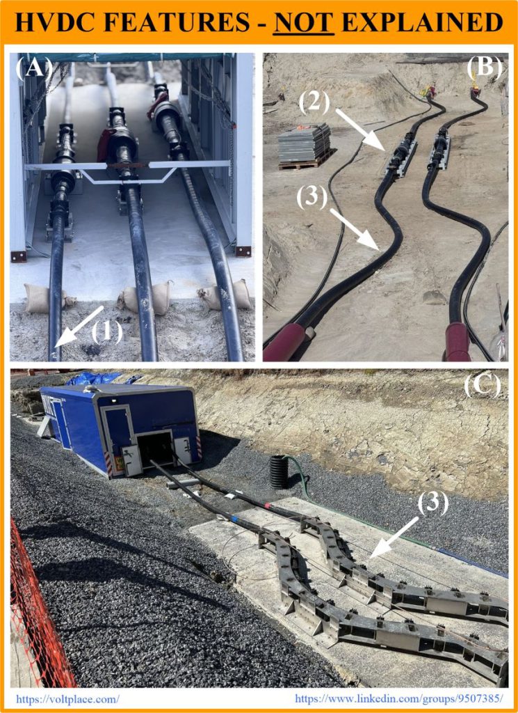
The former ones are practically hidden from us, and all we see is a cable laying vessel on the surface of the water. The second ones are more open, have many photos, which I propose to discuss today (only for the purpose of learning). So, here are three beautiful bipolar HVDC projects, photos of which have been publicly available on LinkedIn over the past month.
(A) – HVDC ±525 kV in Europe, polypropylene;
(B) – HVDC ±525 kV in Europe, XLPE;
(C) – HVDC ±400 kV in the USA, XLPE.
All three projects are the responsibility of the world leaders of the cable industry, built as carefully as possible by highly qualified specialists. However, when considering these projects, the following design questions may arise.
1️⃣ – Return conductor.
It is applied only in the project (A). We see that its diameter is slightly smaller than that of the two poles, and this is expected, because the insulation of the return conductor is thinner than that of the main poles. Questions arise:
🔹 Why this conductor wasn’t located between the poles? It seems that the return conductor can be paired with any of their two poles, and should be in equal conditions with respect to any of them, that is, the return conductor should be located between the poles, not on the edge. Not to mention that it is better to push the poles apart as far as possible to increase the ampacity. Isn’t that right?
🔹 Why does this conductor have XLPE insulation, whereas two poles are insulated by polypropylene? Insulation type can’t be seen from the photo, but it was written in the description of the project. Why couldn’t the whole project be done with cables of the same insulation type? Isn’t that better?
2️⃣ – The base for cable joints.
In projects (A) and (C), the joints are mounted on concrete slabs (the tents above are temporary structures, and we don’t have to pay attention to them). Whereas in the project (B) the joints are fixed on the frame which even has a certain visible flexibility. Isn’t the slab better?
3️⃣ – Laying the cable compensator (“reserve” or “snake”).
A cable reserve is needed to compensate for thermal fluctuations in the length of the cable and sometimes it can also be useful if we need to reinstall the joint. In project (B), the reserve is laid in the ground, and in project (C) it is arranged with a massive metal structure on which the cable is fixed by cleats. Does it seem that the metal structure is redundant?
I would be grateful to the members of the LinkedIn group if they would share their thoughts on topics 1️⃣-2️⃣-3️⃣. You can find the post on HVDC there by the use of the link. Thanks