
Screen cross-section effect
The project usually justifies a specific screen cross-section. However, in practice, there are reasons why the actual screen cross-section may differ from the expected:
1️⃣ The cable was bought from a stock (there was no time to wait since it was a line repair that was required), and as a result, a cable arrived at the facility, with a screen cross-section which turned out to be larger than in the project.
2️⃣ It was decided to combine a new cable production with another, of different screen cross-section (it is cheaper to produce the same type).
3️⃣ Even if a cable with the required screen cross-section was purchased, its actual cross-section is usually slightly larger than the nominal (it depends on the diameter and number of wires, which is known to the manufacturer, but not always known at the design/calculation stage of the line).
If the screen cross-section turned out to be larger, then it seems to be a good thing because “more is not less”. However, in reality, the effect of increasing the screen cross-section is complex. An increase in the screen cross section leads to:
✅ in case of a short circuit: to increase the resistance of the screen to short-circuit currents (this is good);
✅ in normal operation: to an increase in currents induced in solidly bonded/grounded screens and an increase in associated power losses (this is bad).
The first point applies to all 6-500 kV lines, and the second point is more about medium-voltage 6-35 kV lines, because it is there that solid bonding of screens is most common.
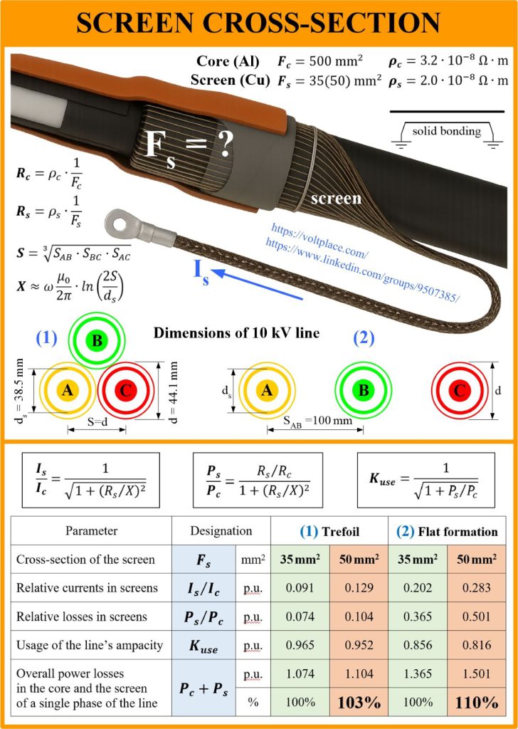
Let us say there is a line U=10 kV, which according to the project was supposed to have a screen cross-section of 35 mm2, but in fact the cross-section turned out to be 50 mm2. Let us evaluate what this led to – calculate the currents and losses in the screens (the formulas are very simple, and are justified in the book). It can be seen:
➡️ increasing the screen cross-section (one step up in the row of nominal values) increased the circulating currents and losses in the screens (in the table – by 3-10% per step);
➡️ the increase in currents and losses is especially noticeable if the project provides for laying single-core cables as flat formation (10% per step).
We see how replacing the screen from 35 to 50 mm2 significantly affects the behaviour of the line. However, even the actual screen cross-section of 36-37 mm2 versus the nominal 35 mm2 would already be capable of increasing line losses by 1-2%. Thus, when performing thermal calculations of lines with solidly bonded screens, it is better to operate with the exact cross-section of the screen, rather than its nominal value.
Another problem is that, as a rule, at the stage of calculations performed by the designer, the actual cross-section (the number of wires and their diameter) is unknown. Therefore, the rhetorical question is whether we need very accurate thermal calculation methods if we do not have accurate data?
We can conclude, as many times before, that with solidly bonded screens:
✅ it is better to lay the phases as close to each other as possible;
✅ it is important not to overestimate the screen cross-section (the required cross-section can be found knowing the magnitude of short circuit current of the network, and its duration); do not let them sell you cables with an incresed screen cross-section.
The difference between the actual cross-section and the design one can easily give a change in cable power loss calculations of up to 1-10%, which means a corresponding decrease of the ampacity of the cable line in question.
You can find cable screen loss calculations in the Part 3 of the book “High Voltage Cable Lines“.