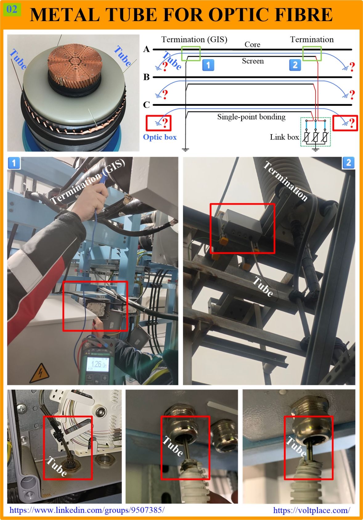
Optic fibre integrated into cable screen
Sometimes optic fibre is embedded in power cables. Such a fibre may be located in a metal protective tube among the wires of the screen. The photo shows an example of such a cable, where 4 metal tubes are placed at once, partly to reserve each other (since fibre is very fragile).
Why is an optic fibre placed inside the cable? Well, it can be used to perform a series of tasks, for example:
✅ temperature monitoring along the line;
✅ vibration monitoring along the line;
✅ monitoring of partial discharges along the line (PDs create microvibration, and this can be used in the future);
✅ the digital connection between the switchgear located at the ends of the line.
Let us look at an example of the practical implementation of nodes where fibre comes out of the cable to the outside. Normally, two things should be done there:
👉 when installing the termination, provide for the output of the optical fibre to the outside not using a metal tube, but using a dielectric tube;
👉 dielectric tubes should be inserted into dielectric “optic boxes” located at the ends of the line, and in such boxes, all connections of the optic fibre of the cable to external devices are performed.
Unfortunately, in practice, there are errors with the arrangement of optical fibre at the ends of the cable line. Let us focus on the case of the cable line with single-point bonding of the screens (this is usually applicable for a line less than 500-800 m long). Single-point bonding of screens is known to be performed to eliminate induced currents in screen and power losses associated with them. For such a bonding, the cable screens at one end of the line are grounded, and at the other they are connected to the Sheath Voltage Limiters (SVL), which are located in the link box and, in normal operation of the line, these SVLs behave like insulators.
The photo shows a case where, for such a line, an optical fibre was taken out of the terminations using a metal tube and metal “optic boxes” were used. If the screens have single-point bonding, but the metal tubes are terminated in metal optic boxes, then, in fact, this will ensure that the cable screens are grounded through this very tube, which can lead to damage to it.
A 110 kV line with single-point bonded screens shown in the photo was laid between:
1️⃣ The Gas Insulated Switchgear (GIS) where the screens were grounded.
2️⃣ A power transformer where the screens were ungrounded (link box with SVLs).
The optic boxes and optic tubes were used which were made of metal. In photo 1️⃣, a man measures the impedance between the housing of the cable termination on GIS side and the housing of the optic box, and it is about 1 Ω.
When the line was energized, each time there was a surge of current in the cable core. This created a voltage impulse on the screen sufficient to ignite a spark between the metal tube and the metal body of the optic box, accompanied by a loud bang (please see a video in the comments).
It was thanks to the loud bang that the situation was noticed in time, the metal optic boxes were replaced with dielectric ones, and serious damage to optic system was avoided.
AFTERWORD 1
There is a video of the spark in the optic box area, taken at the time of energizing the cable line. The video was recorded at the termination 1️⃣ entering the GIS but the situation on the termination 2️⃣ (power transformer side) was almost the same. A ray of light in the darkness.
AFTERWORD 2
It is important to note that there will be problems with metal optic tubes and optic boxes not only for a line where the screens have single-point bonding. There would be problems even if the screens were solidly grounded at the both ends. Regardless the screen bonding type, the fact is that the outer sheath of the cables must be periodically tested with a DC of 10 kV, and during these tests the screens should be completely ungrounded to be able to apply DC voltage between them and the ground – however, even after being ungrounded, the screens remain grounded through the metal tube of the optical fibre and the metal optic boxes. Therefore, at the end of the cables, recommendations for the use of dielectric optic tubes and boxes should be given for all cable lines.