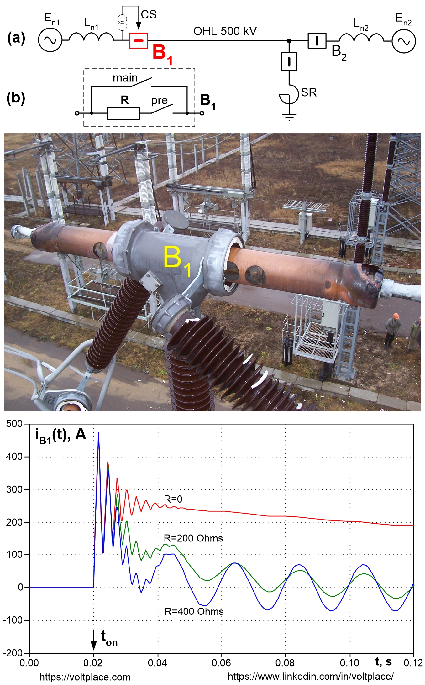
Breaker vs Reactor (part 1)
The photo shows a 500 kV SF6 circuit breaker (B1), which was damaged during the energizing of the 500 kV overhead line. The cause of the accident was the presence of a 500 kV shunt reactor (SR) on the line, which compensated about 100% of the capacitive reactive power of the line. Let’s look at exactly how the reactor managed to defeat the breaker in this case.
Transmission lines (overhead or cable) have a capacitance relative to the ground, and its value depends on:
✅ The length of the line.
✅ Type of the line (overhead or cable).
✅ Phase parameters of the line (number/cross-section of wires of the overhead line or number/cross-section of single-core cables)
As a rule, lines of 330 kV class and above have the largest capacitance. If an AC 50 Hz network voltage (En) is applied to such a line (scheme “a”), then a capacitive current begins to flow through the line, and it leads to effects:
1️⃣ Line generates capacitive reactive power and bring it to the network.
2️⃣ AC 50 Hz voltage rises at the end of the line and may pose a danger.
3️⃣ Phase wires (or cable cores) may be heated or even overheated.
To combat these effects, shunt reactors (SR) are installed in the networks. The reactive power generated by the line capacitance, is consumed in the inductance of the reactor, which reduces the effects of 1-2-3. Reactors can be conventional (with constant inductance) or controlled (with variable inductance). However, in any case, we always try to choose reactors in such a way that they compensate almost 100% of the line’s reactive power. Unfortunately, 100% is not so good.
If the reactor compensates about 100% of line reactive power, then when the line is in no-load mode (scheme “a”), there will be no AC 50 Hz current in the breaker B1. It seems that this is what is needed, but it’s not.
Depending on the moment of switching on (Ton) the line, an aperiodic component of the current will occur in the reactor, and, hence, in the line and its breaker B1. Such a component is shown on the oscillogram and attenuates.
If a quick shutdown is required soon after switching on the line, then breaker B1 will have to turn off the current that does not have zeros, that is, in fact, direct current (DC). The most of SF6 breakers (especially of autocompression type) are not capable of extinguishing the arc of such currents with no zeros. The line shutdown operation will be unsuccessful, the breaker B1 will have an outstanding arc and will be damaged (photo).
To save breaker, the following solutions are known, which should not be forgotten when designing lines:
✅ It is a bad idea to choose a reactor for 100% compensation.
✅ It is better to connect the reactor to the busbars, not to the line.
✅ It is better to use breakers equipped with controlled switching devices (CS, scheme “a”; they catch the moment of closure to reduce the aperiodic) or equipped with pre-switched resistors R (to accelerate the attenuation of the aperiodic current; scheme “b”)