Cable capacitance
Electrical parameters of cables are an important topic. For each line, it is necessary to determine the longitudinal resistance (R) and inductance (L), as well as the transverse capacitance (C), and all these parameters (R,L,C) should be found not only in a positive sequence, but also in a zero sequence.
For overhead lines, these parameters are more or less known, but for cable lines, their calculation sometimes turns into a “journey”:
➡️ The reasons for the problems in determining (R) and (L) are that cables have a wide variety of designs in terms of the presence of metallic elements (screen, sheath, armour), as well as a wide variety of their bonding types.
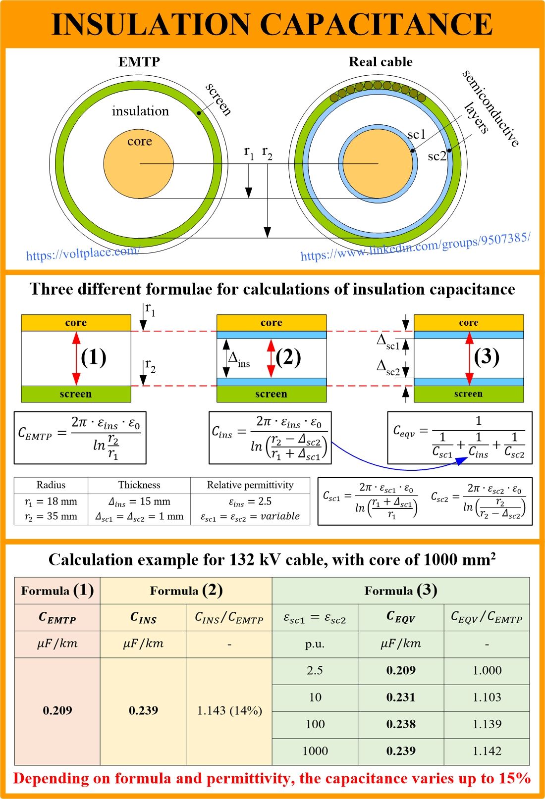
➡️ The reasons for the problems in determining (C) are completely different, and they are related to the fact that the capacitance is affected by dielectric materials located between the core and the screen, among which at least three should be noted:
🔹Semi-conductive layer on the screen (sc1).
🔹Insulation (XLPE, EPR, PP).
🔹Semi-conductive layer on insulation (sc2).
In practice, we can find three different formulae for determining the capacitance (it is the same for the positive and zero sequences):
Formula 1️⃣ – used in ATP/EMTP and similar software;
Formula 2️⃣ – given in standards (IEC 60287 etc);
Formula 3️⃣ – the most accurate (equivalent of all three layers), but requires layers’ permittivity.
The features of formula 1️⃣ are that it is very simple, but it gives an underestimated capacitance, sometimes by 10-20%, which is bad in itself, but also affects things like:
🔹wave impedance;
🔹wave propagation speed.
The special feature of formula 2️⃣ is that it is relatively simple and provides the maximum theoretically possible capacitance. It is useful to have an estimate from above, but for many situations, we need the exact capacitance:
🔹for testing 6-500 kV cables, especially long ones;
🔹to calculate the balance of reactive power;
🔹to solve the issues of neutral grounding;
🔹others.
The special features of formula 3️⃣ are that it is complex and requires information about the permittivity of semi-conductive materials, which is difficult to find, and it remains to be guessed what it is in the wide range from 2.5 to 1000.
Also, all three formulae 1️⃣-2️⃣-3️⃣ have the same problem – it is the permittivity of the main insulation, which can vary from shipment to shipment, and, for example, for XLPE it can be 2.3 to 2.5, that is, it has a deviation of up to 10%.
Thus, there are the following problems with the capacitance:
✅ Which of the three formulae to use for calculations;
✅ What permittivity of the semi-conducting layers to specify;
✅ What permittivity of the main insulation to specify;
✅ How to deal with process modelling in ATP/EMTP.
Originally, calculation of capacitance (C), unlike (R) and (L), seemed as very simple. But we can see that (C) may vary up to 15-20% which is crucial.
You can discuss this and many other issues in LinkedIn cable group. Your opinion is important for the cable industry! Thank you