Cable resistance and inductance – everything is bad!
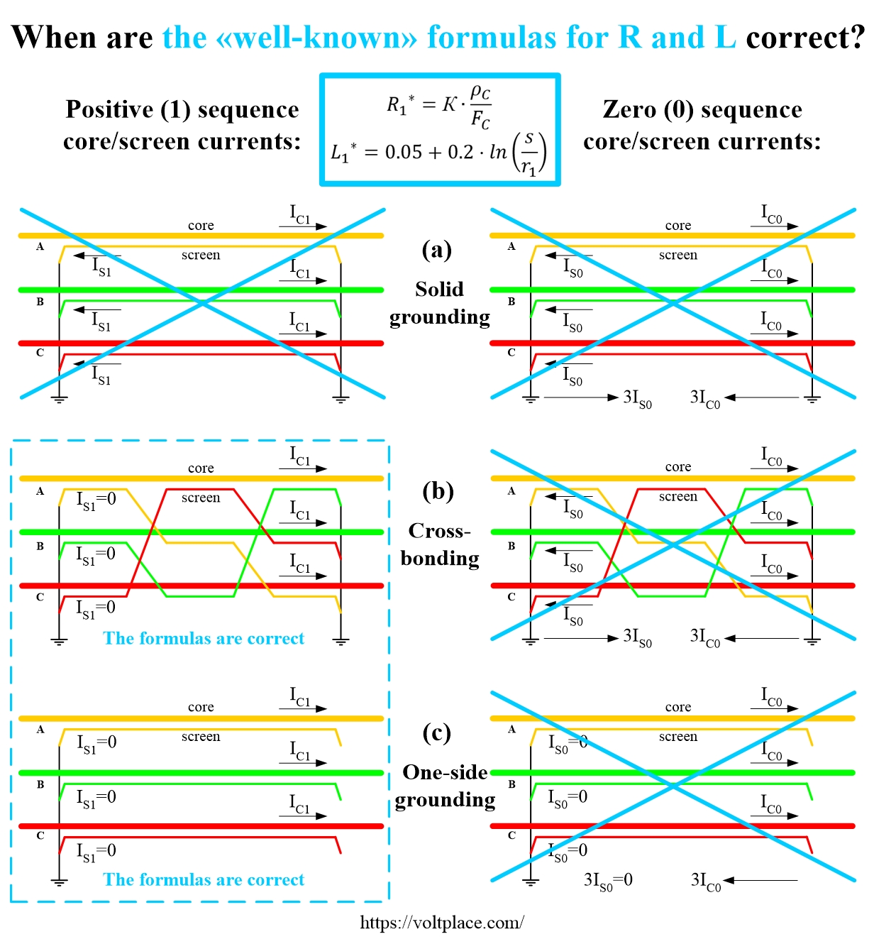
There are «well-known» formulas for calculating the active R and inductive X impedances of the cable line, given in plenty of cable catalogs and regulatory documents. These formulas are shown in the figure. Unfortunately:
1️⃣ They relate exclusively to the case of positive sequence and are inapplicable for zero sequence. That’s why they marked as R1 and X1 (or inductance L1).
2️⃣ Speaking about the positive sequence, these formulas are valid only if there are no induced currents in the screens (Is=0).
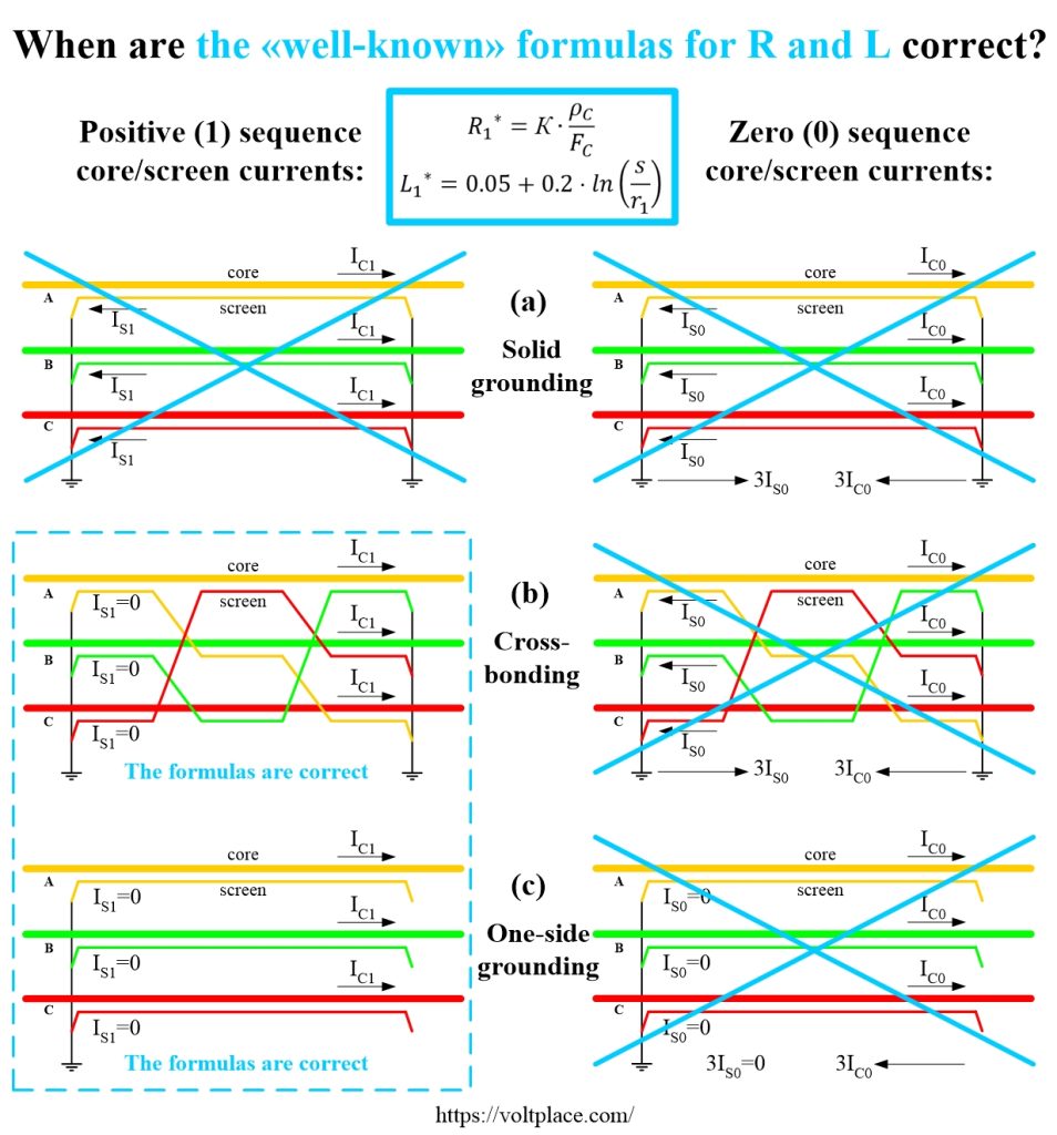
In the figure, in the blue frame are cases when these «well-known» formulas allow you to get correct results:
– positive sequence for cross-bonding (case 1b);
– positive sequence for one-side grounding (case 1c).
In all other cases (1a, 0a, 0b, 0c), these formulas are not applicable, which is shown by crossing them out. Sadly, but catalogues and regulatory documents do not provide formulas that could be used in crossed-out cases. As a result, having no other choice, people use discussed «well-known» formulas for R1 and X1 (or L1) everywhere, which leads to noticeable errors in the calculations of network modes, short-circuit currents, and so on.
Thus, let me please draw your attention:
1️⃣ The positive sequence impedances R1 and X1 significantly depend on the screens grounding scheme (induced currents in the screens influence on the power losses Ps, hidden in R1, and they influence on magnetic field, hidden in X1).
2️⃣ The zero sequence impedances R0 and X0 can be either greater or less than R1 and X1. The specific ratio R0/R1 and X0/X1 depends on the screens grounding scheme, on the cross-sections of the core Fc and the screen Fs, on the distance s between the phases of the line, on the accepted value of the depth Dg of current passage in the ground.
3️⃣ When calculating the operating modes of the network and short-circuit currents, it is impossible:
– assume that active impedances R1 and R0 are noticeably less than the inductive impedances X1 and X0 (neglect of R1 and R0 is permissible for overhead lines and power transformers, but unacceptable for cable lines);
– assume that the zero sequence impedances R0 and X0 are the same as the positive sequence impedances R1 and X1.
After a while, I will share in our group some examples of calculating the parameters of 6-500 kV cable lines. You will see how significant and dangerous errors can be if «well-known» formulas for R1 and X1 from catalogs are used everywhere without taking into account the sequence (positive/zero) and screens’ cross-section Fs and their grounding scheme.
To emphasize the danger of the situation, I must say that these «well-known» formulas for R1 and X1 (or L1) are included not only in catalogs and regulatory documents, but also in a number of expensive professional software for calculating:
– cable lines themselves;
– normal operational modes of the network;
– short-circuit currents of the network.