
Cable wave impedance
Sooner or later, we will make a series of posts about wave processes in cable lines. Understanding these processes allows, for example, to solve the following tasks:
1️⃣ Determine the core current when the cable is energized.
2️⃣ Determine, for cable lines with single-side grounding of the screens, on which of the two sides it is better to ground the cable screen, and on which side it is better to leave it ungrounded.
3️⃣ Prove that in many of the cases, no sheath voltage limiters (SVL) are needed in the cable screens at all.
4️⃣ Select SVL characteristics where such SVLs are really needed.
However, let’s start in order – today’s post is about the fact that the wave impedance (Zw) of a cable is not one thing at all, as cable catalogues teach us. In fact, a cable line can have several wave impedances at once, depending on the bonding/grounding scheme of the screen and the laying conditions of the cables. So, the wave impedance of a cable is somewhat more complicated than just the square root of the cable’s inductance divided by its capacitance. And this is so, if only because the inductance and capacitance of the cable depends on the bonding/grounding scheme of the screens, as well as on which side the wave comes into the cable.
Wave impedance characterizes the relationship between voltage (U) and current (I) waves propagating along a cable. Waves can occur due to the arrival of lightning or switching waves to the cable. Switching waves occur, for example, at the moment when a cable line is energized (the magnitude of such a wave is equal to the amplitude of phase-to-ground voltage of the grid).
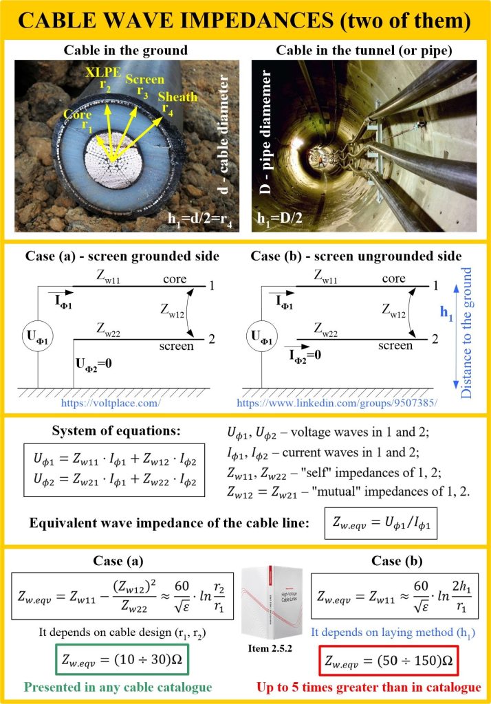
The photo shows two cases of cables with their screens:
➡️ Case (a) – the wave comes from the side where the cable screen is grounded.
➡️ Case (b) – the wave comes from the side where the cable screen is ungrounded.
Item 2.5.2 of the book shows that in this case, the cable line will have completely different input equivalent wave impedances (Zw.eqv). In the case of (a), the impedance is determined by the radius of the core (r1) and XLPE insulation (r2), but in the case of (b), the impedance depends on the distance from the core of the cable to the surface of the zero potential (h1):
✅ when laying in the ground, h1 =d/2, where d is the diameter of the cable;
✅ when laying in a PE/PVC pipe, h1=D/2, where D is the outer diameter of the pipe;
✅ when laying in a concrete tunnel, h1=D/2, where D is the inner diameter of the tunnel.
For example, this means that when a cable line is energized, current impulses can vary up to 5 times, depending on which side of the line the grid voltage is applied. If we want to limit current impulses when the cable line is switched on, then it must be energized on the side where the input wave impedance is greater. That is, from the side where the screens are ungrounded – case (b).
PS
Today we talked about the wave impedance in the transient mode. The wave impedance for steady-state mode is always the wave impedance of case (a), regardless of the bonding/grounding scheme of the screens. It is used to calculate the AC 50 Hz voltage rise at the end of the line, to calculate the reactive power balance, and so on. We can see that the cable line has many different wave impedances, depending on the problem being solved. And certainly not one!