
Positive sequence impedance of the cable line
We hear a lot that “green transition” is impossible without cable lines. But do we know and understand cable lines that well? Unfortunately, I have to say that we do not know them very well, and so far, the cable standards and catalogues require improvement. Let me show this using the example of the longitudinal active (R) and inductive (X) impedances of cable lines.
Today we will focus only on the positive sequence (R1, X1), and we will discuss the zero sequence (R0, X0) next time.
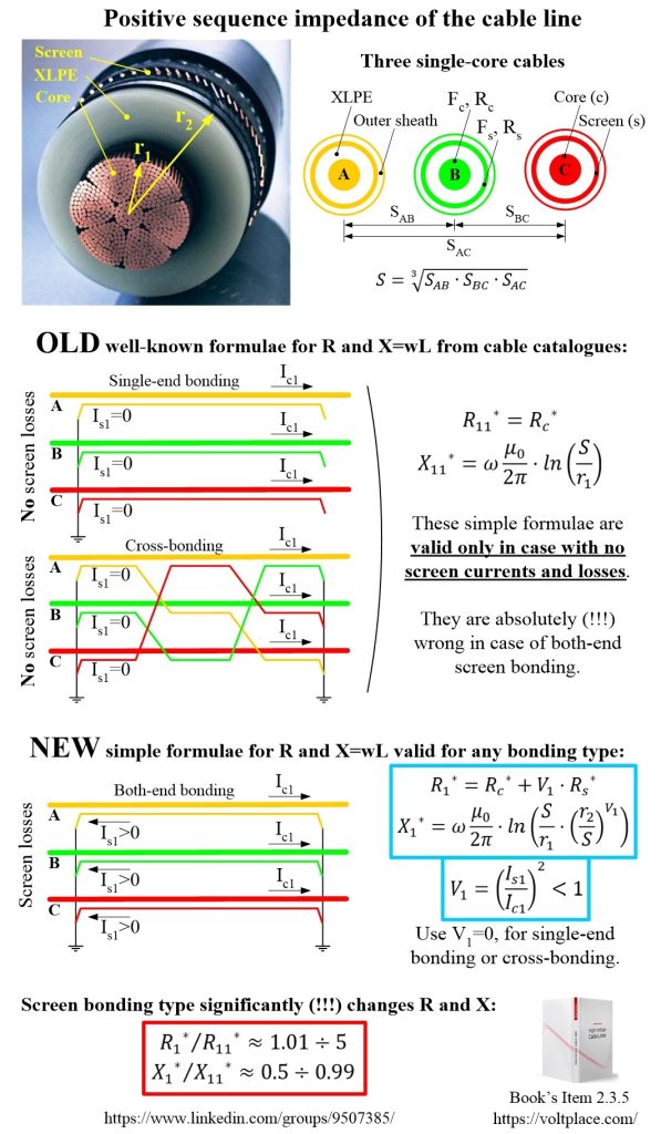
Currently R1 and X1 of the cable line are calculated using simple well-known formulae (in the photo they are R11 and X11). Their problem lies in the fact that R11 and X11 do not take into account the material and cross-section of the screen Fs, which means they are valid only for the case without currents and losses in the screens, that is:
✅ for lines with single-end bonding;
✅ for lines with cross-bonding.
At the same time, the formulae R11 and X11 are mistakenly widely used to calculate the parameters of cable lines with both-side bonding. Apparently, this happens for the following reasons:
1️⃣ it seems to people that the error will be small;
2️⃣ people simply do not have formulae to calculate the correct parameters.
Chapter 2.5 of the book “High Voltage Cable Lines” is devoted to this issue, where it is shown:
✅ that the error in impedances can be significant, reaching 2-5 times, and thus it is impossible to apply the well-known formulae R11 and X11 for the case of both-side bonding;
✅ how to find simple, accurate universal formulae for calculating R1 and X1 for any screen bonding type.
Note, that both-side bonding is most often found in medium voltage networks of 6-35 kV. Therefore, it is in such networks that calculating the parameters of cable lines using the well-known formulae R11 and X11, which do not take into account the processes in the screens, can give serious errors and the most dangerous consequences.
Let me please remind, that impedances R1 and X1 directly affect the currents and voltages in the network in normal mode. Also, of course, R1 and X1 affect the magnitude of short-circuit currents, which means that these impedances influence on:
✅ selection of circuit breakers;
✅ thermal and dynamic stability of the equipment;
✅ possibility of fires;
✅ potentials on grounding systems, and, hence, personnel safety;
✅ issues of electromagnetic compatibility of network equipment;
✅ protection and automation.
Imagine that when designing a 6-35 kV cable network, all lines, of which there are dozens, had incorrect impedances R1 and X1 included in the calculations. Of course, in such a situation, it can easily turn out that the real short-circuit currents of the network will be, for example, 20-30% more than those that we expected using incorrect R11 and X11, and which the equipment mistakenly counted on. So, this is a disaster, and fixing the situation with impedances of cable lines is very important for our industry.