Screen bonding cable length
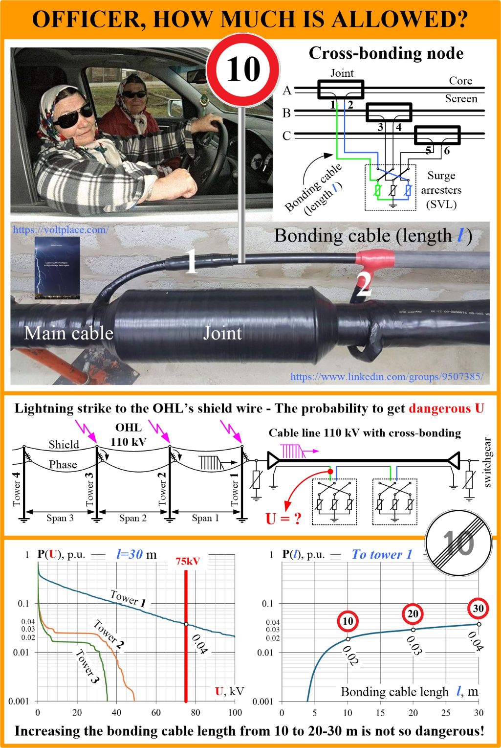
We know that the screen’s cross-bonding is an effective way to deal with induced currents and losses in the screens of 6-500 kV cable lines (CL). The use of cross-bonding allows not only to save on losses (dozens of thousands of euros annually), but also to increase the permissible core current of the cable line, sometimes by 40-50%. When performing the cross-bonding, the cable screens are connected with link box using special bonding cables. Inside the box, there are metal jumpers and surge arresters (sheath voltage limiters, SVL).
When using bonding cables, three questions arise:
1️⃣ What type of bonding cable to choose?
2️⃣ What kind of impulse processes to consider?
3️⃣ What is the acceptable bonding cable length?
We have already discussed issues 1 and 2. It has been shown that, contrary to CIGRE’s estimates:
✅ A coaxial bonding cable has no great advantages over two separate single-core bonding cables;
✅ Lightning processes are crucial only for 6-110 kV lines, and switching processes are crucial for 220-500 kV lines.
We will continue to explain 1 and 2. However, today let us focus on 3.
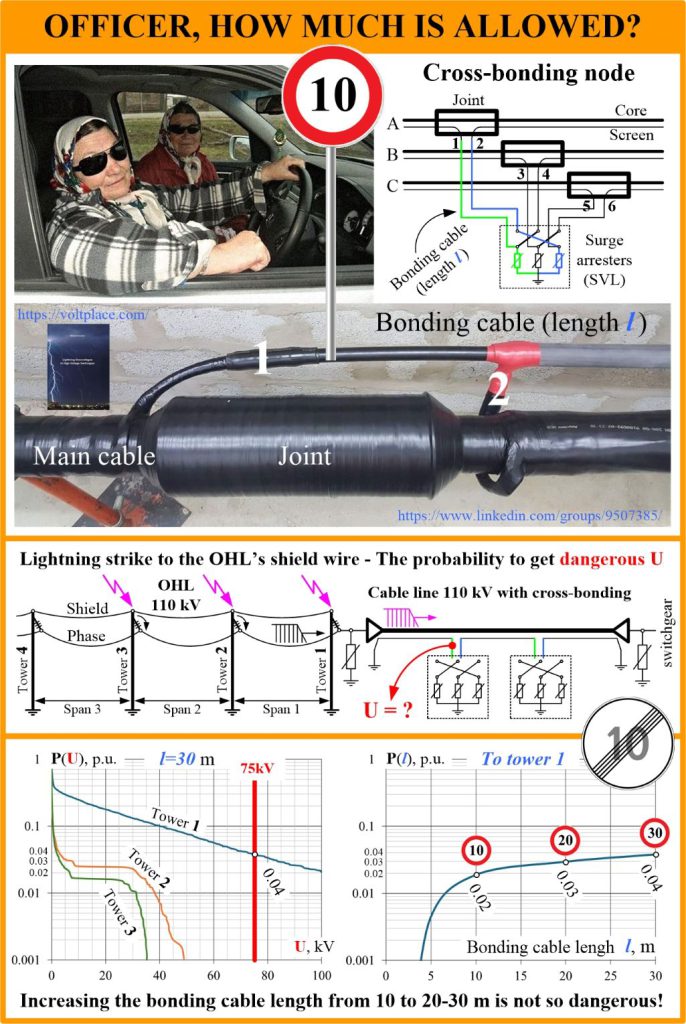
CIGRE gives a formula for calculating the lightning voltage peak (U) on the cable screen in the joint. This formula is the sum of the voltage drop across the SVL (its residual voltage) and on the bonding cables between the SVL and the joint. To calculate the voltage U, we have to set the inductance of the bonding cable and the steepness of the current impulse.
By setting the specific steepness of the impulse, CIGRE obtained that a bonding cable length of 10 m is the maximum allowable. However, a reasonable question arises – where did this particular steepness of the current come from? Everyone knows that the processes during lightning discharges are statistical in nature, and the steepness can be almost any!
The steepness depends on dozens of factors, including:
➡️ parameters of the lightning current strike;
➡️ the specific site of the strike to the OHL (to the shield or phase wire);
➡️ the type of OHL tower, voltage class etc.;
➡️ the impulse strength of the OHL’s insulation string;
➡️ the distance between the lightning strike site to the OHL and the cable line.
None of this can be found in CIGRE, and we should fix this. Let me present calculations of the probability of occurrence of lightning surges of dangerous peak in the cross-bonding node of the 110 kV cable line. As we can see, even for the bonding length of 30 m, some kind of danger occurs only if there is a lightning strike to the OHL in the immediate vicinity of the CL (in fact, a strike to the tower of the transition point).
The probability of danger to joint increases with increasing the length of the bonding cable. If we have 30 meters instead of 10, nothing will happen. The only thing is that the probability will increase by 2 times (from 0.02 to 0.04). That is, there is no disaster if we have a length of more than 10 m.
According to IEC 60840, for 36-170 kV cables, the lightning impulse test voltage is:
🔹75 kV, inside the joint at the gap between the screens;
🔹37.5 kV, on the screen relative to the ground.
According to our experience, 110-500 kV class cables have a real impulse strength of several times greater. For instance, for 110 kV line it can be taken as 100 kV and even higher. Today we took 75 kV, instead of 37.5 kV per IEC.
However, regardless of the strength, the result will the same – if we need to have 15-20 m (instead of 3-10 m), highly likely we can do it. The difference in probabilities for 10, 20 and 30 m will not be so noticeable to strictly prohibit to have more than 10 m. Once again – lightning calculations are about statistics and not about single formula with the predefined front steepness.
By the way, talking about the length, we need to think about switching as well. As it was shown in the book, switching is crucial for 220-500 kV lines (not 110 kV). Unfortunately, CIGRE talks about lightning only. Hope to fix it sometime.