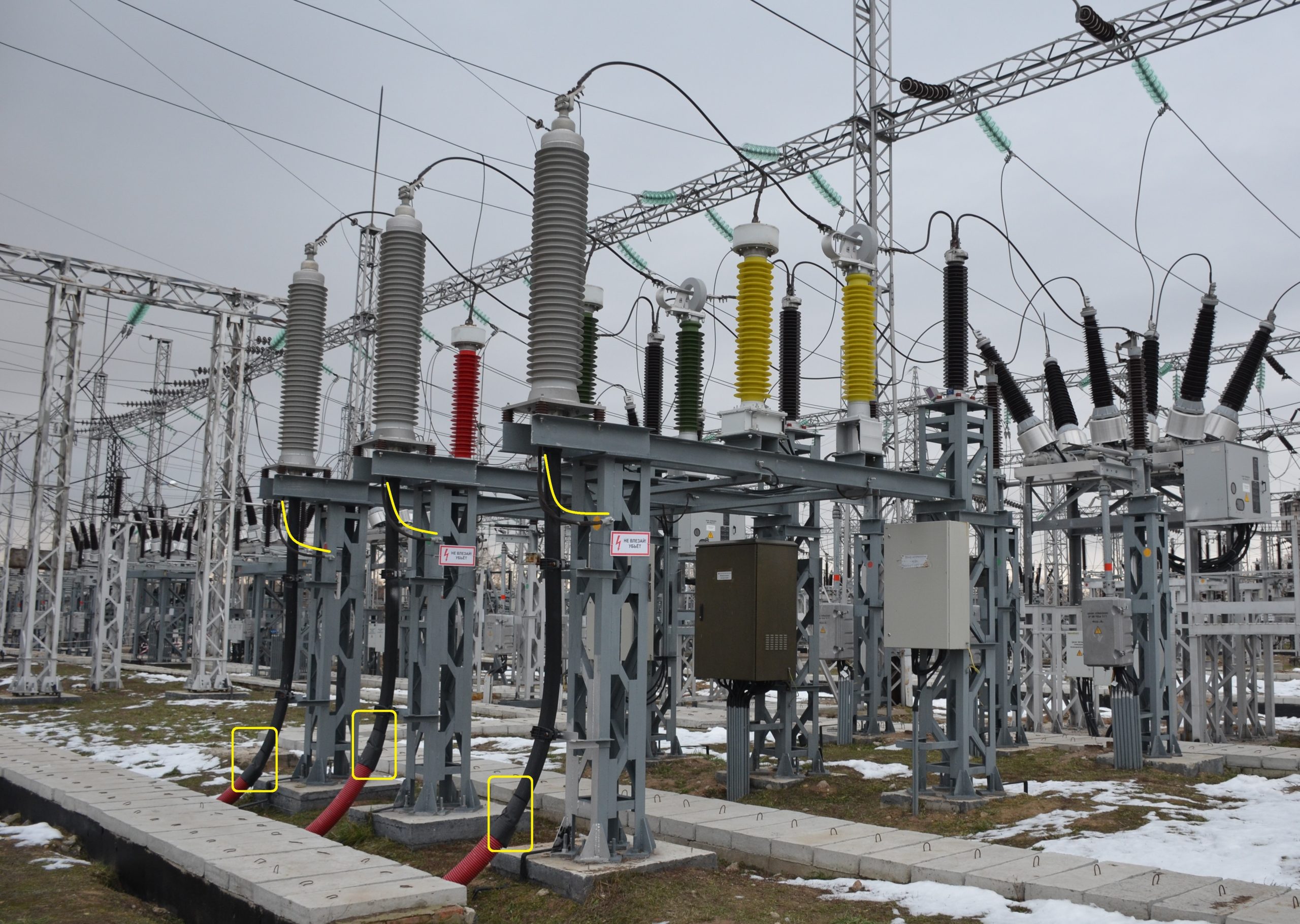
The case of cable terminations in the 110 kV switchgear
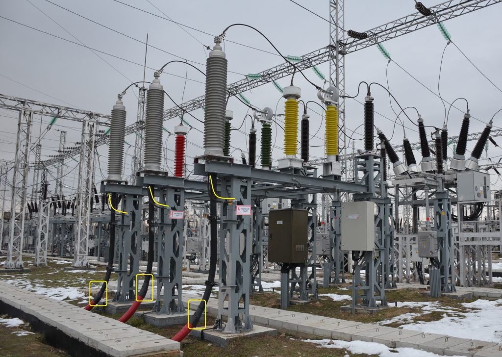
1️⃣ As you can see from the photo, the cable screens are grounded directly to the support structure, without the use of link-boxes (I marked screens with yellow lines). This kind of screens connection is not a good solution, because it creates problems for personnel during periodic tests of the cable outer sheath.
Let me remind you that, according to IEC, during such tests, the cable line is disconnected from the network, its screens are ungrounded, and a DC voltage of 10 kV level is connected to the screens for a period of 1 min in order to check the integrety of cable outer sheath and absence of water penetration risks to main XLPE insulation. Usually it is more convenient and safer to make such a testing if the screens have connection through link-boxes. In the switchgear, such link-boxes are placed not at height, but at ground level, so that personnel wouldn’t have to use a ladder. So in the photo, the problem is not only in the absence of link-boxes, but also in the fact that the screens grounding point is too high from the ground.
2️⃣ The cables themselves in the section from the terminations to the concrete tray are laid in corrugated pipes. Such pipes, unfortunately, usually do not have UV protection and are generally flammable. That is, I am confused by these pipes. But the ends of the pipes, on the contrary, I like. Personnel tried to close them not with short-lived mounting foam, but with something more reliable and durable. It seems that the pipes have some kind of black tape (such a tape will be easier to remove, unlike a heat-shrinkable tube).
3️⃣ Please pay attention to the high-voltage measuring current and voltage transformers mounting next to cable termination. They are in phases A, B, and C, respectively, of yellow, green, and red colour. It is convenient enough to determine the phase of the equipment.