The system of correction factors
In cable catalogues, in addition to the main types of cables, there are simplified recommendations on cable selection. They are given as a table with capacity currents for basic laying conditions (Ib), as well as a series of 5-8 additional tables with various correction factors (K). It is important to note that the system of factors is very approximate, and the resulting capacity error can reach 20-30% (1-2 steps in the row of standard core cross-sections).
The system of factors may include at least:
K1 – for the ground temperature;
K2 – for the installation depth;
K3 – for the thermal resistivity of the soil;
K4 – for the distance between phases (if single-core cables);
K5 – for the number of circuits and distance between them;
K6 – for the installation in pipes (ducts, conduits);
K7 – for the screen losses;
K8 – for the load graph irregularity (load factor).
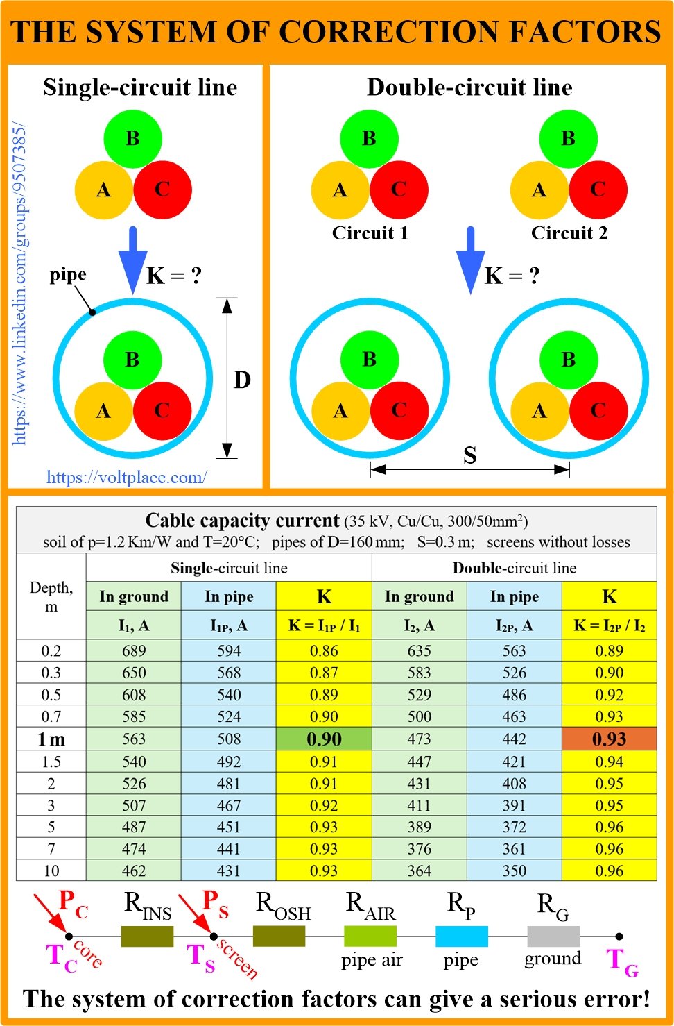
If the various features of laying the cable line did not affect each other, then the capacity current could be represented as the multiplication of the base current (Ib) by all factors I=Ib*K1*K2*…K8. However, the problem lies in the fact that the laying conditions affect each other and cannot be described by the system of independent factors. Let us show this using the example of the well-known coefficient for laying in pipes. Any catalogue indicates that if cables are placed in pipes, K6=0.9, that is, the pipe reduces the ability of the cable to cool and takes up 10% of the capacity.
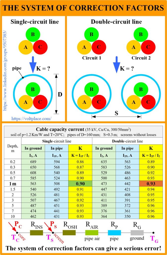
Let us calculate the capacity in such a way as to understand how the pipe affects the current depending on the depth and the number of circuits. The table shows:
➡️ for single-circuit line, the factor K6 changes from 0.86 to 0.93.
➡️ for double-circuit line, the factor K6 changes from 0.89 to 0.96.
With the help of software, for single-circuit line, with a depth of 1 m, the factor is indeed K6=0.9, as promised by the catalogues. For double-circuit line, at the same depth, the factor is K6=0.93. Thus, we see that the pipe factor depends on:
✅ the number of circuits.
✅ the depth.
How do we understand that a pipe affects in such a complex way? Let us look at the thermal diagram of the cable in the pipe. The thermal resistances R of the insulation, the outer sheath, the air (in the pipe) and the pipe side wall obviously do not depend on the depth. However, the resistance Rg of the ground increases as we move deeper away from the earth’s surface. Thus, as the depth increases, the role of Rair and Rpipe becomes less noticeable against the background of the great Rg. So is it any wonder that at deeper depths, the pipe affects less, and the correction factor K6 for the pipe turns out to be close to 1 (and not 0.9).
We can see that the system of correction factors offered in the catalogues can be used for preliminary cable selection, and the final selection must be done using detailed thermal calculation. Otherwise, the total error can reach 20-30%.