
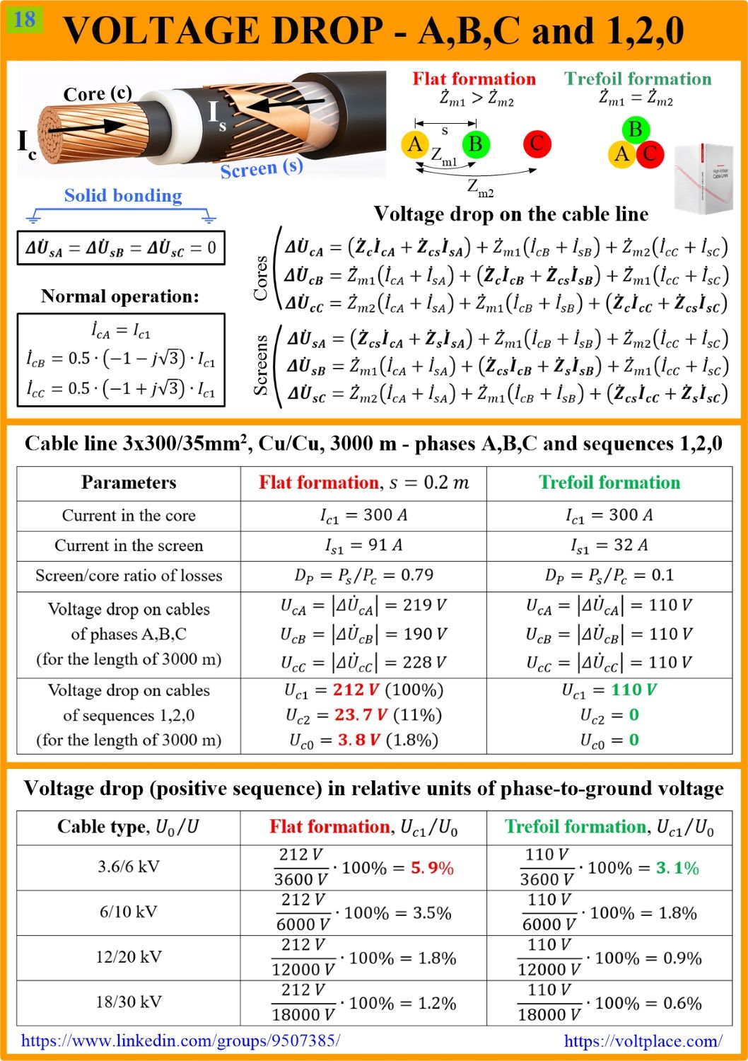
Voltage drop on the cable line
The voltage at the ends of the line may differ from each other. This is due to the fact that the line has an active-inductive impedance, which causes a voltage drop from the following currents:
✅ the load current passing through the line to consumers.
✅ the capacitive current generated by the line and passing from the line to both its ends (the distribution of this current is determined by calculating the network mode, taking into account the balance of reactive power).
For 3-35 kV lines, usually having a length of up to 3-5 km, the capacitive current does not exceed a dozen Amperes, and it can be neglected against the background of a load current reaching hundreds of Amperes – this simplifies calculations of the voltage drop. However, there is a factor complicating the calculations – this is the solid bonding of the screens which is typical for most of 3-35 kV lines. The solid bonding means that induced currents occur in the screens, which change the impedance of the line:
➡️ the active impedance increases (since the line has more losses).
➡️ the inductive impedance decreases (since the current in the screen is usually passes in the opposite direction to the current in the core).
Let us give an example of a calculation for a single-circuit line made by three Cu300/Cu35 mm2 single-core cables with a core current of 300 A. To do this, we have to prepare the system of 6 equations, written in complex numbers (the designations are taken from Part 2 of the book “High Voltage Cable Lines”). Taking into account the solid bonding of the screens and the fact that the load current in the cores is a positive sequence current, we solve the system and get the voltage drop in phases A,B,C.
It can be seen that for a flat formation the voltage drop:
✅ is about 2 times higher than for a trefoil.
✅ differs significantly between phases A,B,C.
The latter circumstance means that in normal operation the voltage drop is not of a positive sequence, but contains three sequences at once! After converting from A-B-C to 1-2-0, we obtain the following voltage drop:
1️⃣ 212 V of positive.
2️⃣ 23.7 V of negative (or 11% of the positive).
⭕ 3.8 V of zero (or 1.8% of the positive).
Thus, when laying in a flat, even if at the beginning of the line the voltage is symmetric (of the positive sequence), at the end of the line it will receive noticeable components of the negative and zero sequences. Note that such an asymmetric result cannot be obtained if we calculate the voltage drop on the line by multiplying the load current and the impedance of the line.
In addition, we see that voltage drop issues (like many others) show us the importance of choosing the right phase arrangement – a trefoil should be preferred for all 3-35 kV lines.
Fortunately, for lengths less than 3-5 km, the voltage drop is noticeable only for 3-10 kV lines. As for the 20-30 kV lines, the voltage drop is not an important factor (see the table).
You can discuss this post on LinkedIn, in the “High Voltage Cable Lines” group, by following the link to the post.
AFTERWORD
One of the ideas of the post is to show that when laying in a flat, in normal mode, the voltage drop on the line is not equal to the positive sequence current (Ic1) multiplied by the line impedance of the positive sequence (Z1). To fix the problem of different voltage drops in phases A,B,C, we can do one of two following things:
✅ lay the cables in a trefoil (as it was recommended in the post).
✅ make periodic changes in the position of cables A,B,C (not to be confused with the cross-bonding of the screens).