
Checking the cross-bonding of cable screens
If the HVAC cable has a fault of its “core insulation”, then there is a current which is significantly higher than in normal operation. Therefore, the protection sees such damage well, and the line can be quickly disconnected. But what happens if we have a damage to the “screen insulation” (outer sheath or link box)?
If this damage has occurred, it is not a short circuit, it almost does not change the currents in the cores and cannot be determined by protection. A line with a damaged sheath can be operated for years until one of the following happens:
✅ damage will be detected during sheath testing (with DC 5-10 kV);
✅ damage will cause so much water to enter the cable that it will lead to a fault of the “core’s insulation”, that is a short circuit.
If the line is working and there is damage to the link box, then current passes there from the screen to the ground, and this creates risks of touch voltage and step voltage, as it was discussed in the previous post #26. Therefore, it seems reasonable to equip the line with automatic signalization about sheath damages. However, it wouldn’t be easy, and this is described below.
INTRODUCTION:
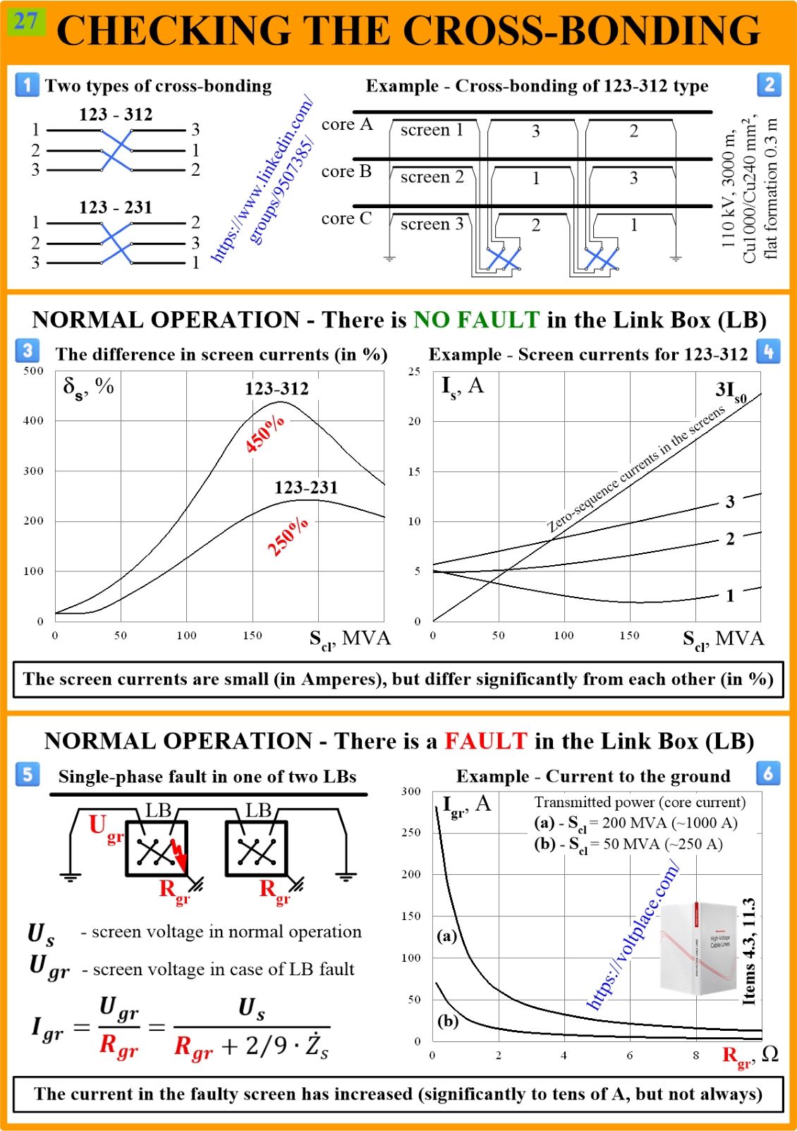
1️⃣ There are two different types of cross-bonding (book’s Item 4.3). This affects screen currents in normal operation but few of us know this, and this is not described in the regulatory documents.
2️⃣ There is an example of a cross-bonding of the 123-312 type.
NO DAMAGE:
3️⃣ There is an example of currents in screens 1,2,3 in relative units (in %), depending on the power (Scl) transmitted over the 110 kV cable line. It can be seen that the screen currents can differ up to 5 times (450%), although there is no damage to the sheath. This is due to the fact that when laying single-core cables in a flat formation, induced (inductive) currents of the zero sequence occur in the screens, and they are summed up here with capacitive currents of the positive sequence. This is the reason for the difference in currents in screens 1,2,3.
4️⃣ There is an example of currents in screens 1,2,3 in absolute units (in Amperes). It shows the current of the zero sequence and the resulting currents in screens 1,2,3. The resulting currents differ in three screens 1,2,3 although there is no damage, and therefore it is impossible to build protection by comparing these screen currents.
WITH DAMAGE:
5️⃣ There is a line with a damage to one of the three phases, in one of two boxes. The formula for calculating 50 Hz current (Igr) in the screen is taken from book’s Item 11.3. Also it can be easily derived from the formula for screen voltage (Ugr) presented in the previous post #26.
6️⃣ There is a graph showing how the screen (or screen-to-ground) current (Igr) in the damaged point depends on the grounding resistance (Rgr) and the transmitted power (Scl). It can be seen that at resistances of more than Rgr = 1 Ω and with a low load (Scl < 50 MVA), the current in the screen (Igr) is no more than 20-30 A, and this differs little from the currents in case 4️⃣ with no damage.
THE MAIN QUESTION:
How can we automate the protection of the line from sheath damage if the currents of the screens are small both in the absence of damage and in its presence? There is no answer, but it would be very useful to solve the problem because this is important for the safety of people at the link boxes and their manholes (because of touch and step voltages)!
You can discuss this post on LinkedIn, in the “High Voltage Cable Lines” group, by following the link to the post.
COMMENT 1
The greater the power (Scl), the greater the current in the core (Ic), the greater the induced voltage on the screen in the cross-bonding node (Us), the greater the voltage on the box body when it is damaged (Ugr), the greater the current (Igr) in the screen of the corresponding phase, and the easier it is to see that this current (Igr) differs in magnitude from the currents of the other two screens, which don’t have any sheath damage.
The problem of building a line protection against damage to the sheath is that current of the screen of the damaged phase (Igr) can be very small, which is typical if the cross-bonding nodes are poorly grounded (Rgr > 1 Ω) or if low power is transmitted over the line (Scl < 50 MVA). In the case when these two conditions are met, the current in the screen (Igr) is minimal, and the sheath protection will not be able to distinguish it from the current in normal mode with no damage to the sheath and link boxes. However, the touch/step voltage will be also minimal, that is, the danger to people is also not great.
COMMENT 2
Posts #26 and #27 consider the ideal balanced cross-bonding. However, if the lengths of the sections are different (not equal to 1/3 of the length of the line), then the situation becomes noticeably more complicated, making it even more impossible to build protection against damage to the sheath. This means that the problem of human safety in the cross-bonding nodes remains unresolved.
All that can be suggested today is not to build cable lines where, in normal operation mode without sheath damage, the induced voltage (Us) at the cross-bonding node is more than 100 V, as it was shown in the previous post #26.