
Average distance between cables
Most 6-500 kV (AC or DC) cable lines are made of single-core cables. At the same time, different laying methods may occur along the line. For example, for three-phase AC there are following well-known options:
✅ Laying in trefoil;
✅ Laying in pipes/ducts;
✅ Laying in flat.
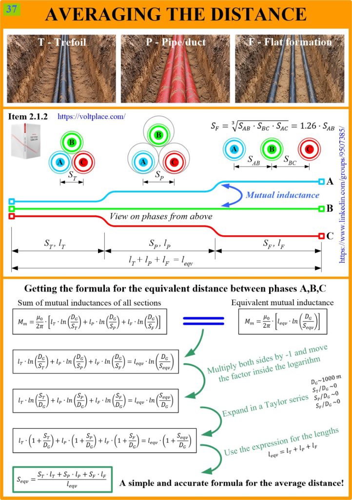
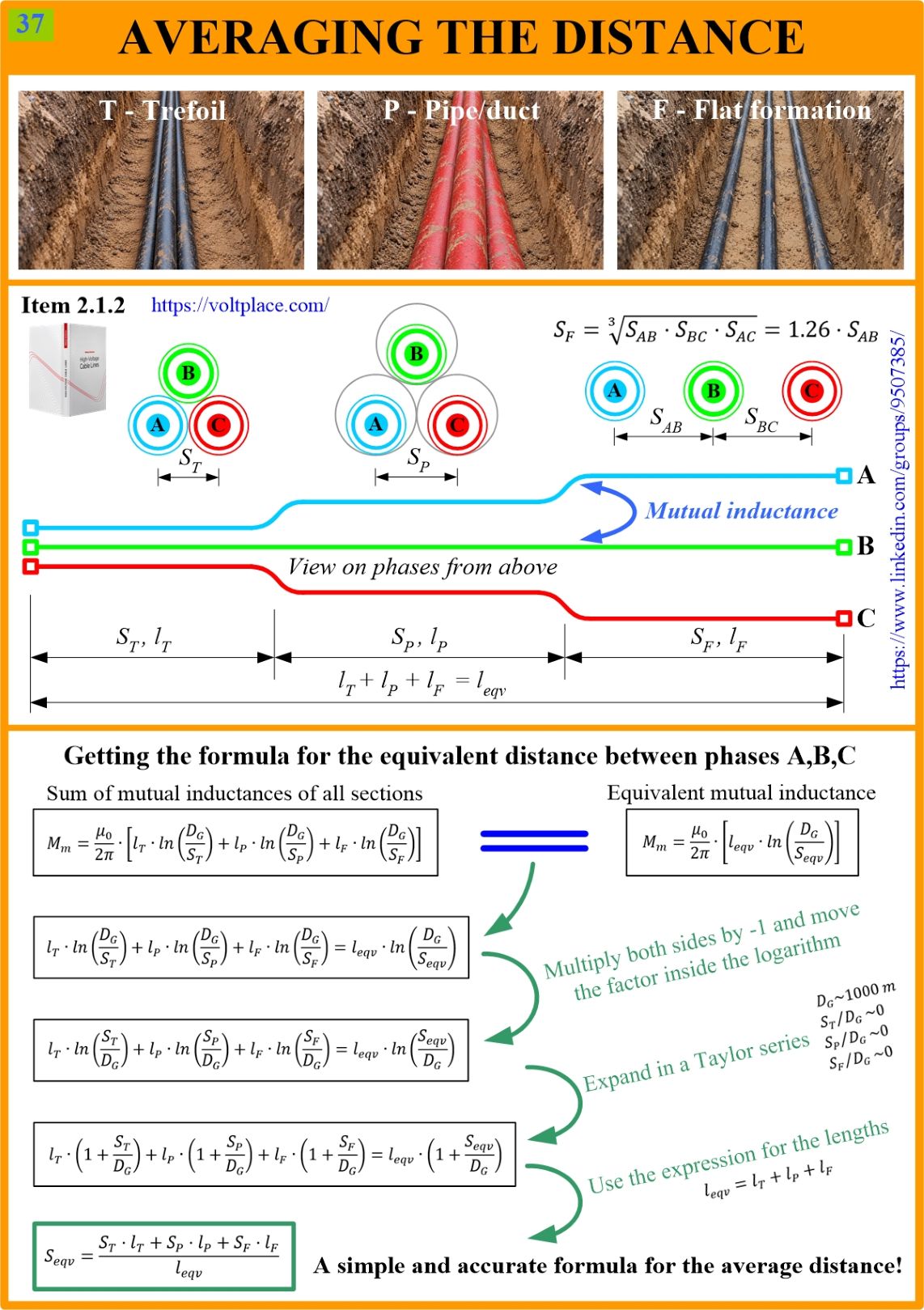
The presence of sections with different mutual arrangement of phases increases the number of thermal calculations of the line that must be carried out to select a sufficient cross-section of the cable core. However, before thermal calculations, it is necessary to choose a screen bonding type, since it determines the level of power losses in the screens and directly affects the resulting temperature of the cables. Main types of screen bonding (solid bonding, single-point bonding, cross-bonding) differ significantly in the values of induced currents (losses) and voltages in the screens.
Screen currents (losses) and voltages are determined by the mutual inductance between the phases, but this inductance varies along the line, because the ways of laying the phases are not the same. Therefore, when performing calculations, it is necessary to find the mutual inductance for each laying method (trefoil, pipes, flat), considering the length of the method, and then sum up the found mutual inductances to get the total (Mm). This section-by-section calculation require many mathematical operations and may cause accidental errors.
Fortunately, there is a solution – calculate the average (equivalent) distance (Seqv) for the laying methods (trefoil, pipes, flat) and then deal only with this equivalent (Seqv) and calculate the mutual inductance (Mm) based on it.
The formula (Seqv) is shown at the bottom of the slide and, due to its simplicity, does not seem to be accurate enough. However, this is not the case, and the formula has a strict mathematical justification based on the decomposition of the logarithm into the Taylor series. The corresponding math operations are shown on the slide.
For example, let it be necessary to calculate the voltages in the nodes of the cross-bonding of the screens, as it was in post #36. The line is divided into three minor sections with lengths L1, L2, L3, but we cannot proceed with voltage calculations since each of these three sections has several laying options of phases. To solve the problem, we need to:
➡️ find the equivalent distance S1eqv for the 1st minor section L1;
➡️ find the equivalent distance S2eqv for the 2nd minor section L2;
➡️ find the equivalent distance S3eqv for the 3rd minor section L3;
➡️ calculate screen voltages (Us) per post #36.
Once again, the formula for the average distance between phases (Seqv) is simple, but at the same time precise and allows us to calculate any screen bonding using the method of the book, without involving matrices, complex numbers, computer modelling and other “too smart” things.
You can discuss this post on LinkedIn, in the “High Voltage Cable Lines” group, by following the link to the post.