
Cable temperature calculations
The thermal calculation of the line is an important section of the project. When performing calculations, it is necessary to carefully consider the laying conditions, soil and air parameters, the presence of pipes, parallel circuits, and third-party heat sources. If the line is consists of single-core cables, then additionally it is necessary to take into account:
✅ the formation of the three phases (trefoil or flat, etc.).
✅ the bonding type of the screens (with or without losses).
In general, at least 4 options should be considered:
1️⃣ Trefoil formation, no screen losses (single-point bonding or cross-bonding).
2️⃣ Trefoil formation, with screen losses (solid bonding).
3️⃣ Flat formation, no screen losses (single-point bonding or cross-bonding).
4️⃣ Flat formation, with screen losses (solid bonding).
Let us look at 4 options using the example of a single-circuit medium-voltage line. For certainty, we will make calculations for XLPE-insulated 500/120 cables with a copper core and screen. Let the cables be laid in the ground with a thermal resistance of 1.2 Km/W and a temperature of 20℃.
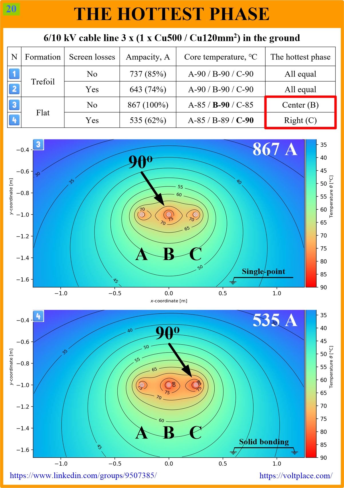
The results by “Cableizer” are shown in the table, and we can see how strongly the permissible current depends on the phase arrangement and bonding type. If they are chosen incorrectly, the line can lose up to half of its ampacity. For example, if we take ampacity 3️⃣ as the best option (100%), then the worst option 4️⃣ will give only 62%. Do not forget what is not visible in ampacity calculations – the cost of losses in screens which, depending on the length of the line, can reach up to tens of thousands of euros annually.
However, let us talk about something else – which of the three phases is the most overheated? The table shows the core temperatures for each of the phases (left A, center B, right C). It can be seen that when laying in flat, the temperature of the most heated and least heated cores can vary up to 5℃! At the same time, the most heated is:
3️⃣ – the middle phase.
4️⃣ – the right phase (if you look in the direction of power transmission) or so-called “lagging phase”.
The temperature difference in case 3️⃣ is obviously explained by the different cooling conditions for the extreme and middle phases. The temperature difference in case 4️⃣ is explained by the fact that the three phases have different induced currents in the screens and different losses in the screens. As a result, despite the best cooling for the middle phase, it is the extreme phase C that is heated, where losses in the screens are maximum.
Calculating losses in screens A, B, and C when laying phases in a flat and there is no phase transposition of phases (not to be confused with screen cross-bonding) is not the easiest task. For example, formulas are given in IEC 60287. In one of the following posts, we will show why these formulas give the difference in losses in the three phases about 5% less than it actually can be.
You can discuss this post on LinkedIn, in the “High Voltage Cable Lines” group, by following the link to the post.
AFTERWORD
The temperature difference in case 4️⃣ is very interesting. It is caused by the different conditions in which the screens of phases A, B, and C are. Due to this, not only positive sequence currents (Is1) arise in the solidly bonded screens, but also negative (Is2) and even zero sequence currents (Is0). All this leads to the fact that in the direction of power transmission, the right phase will be the most problematic (phase C or the “lagging phase”).
If the direction of the power transmission is the same during the day or year, then the asymmetry of the thermal field of the cable line will be quite stable. And it will allow us to give the following rather comic recommendations:
✅ if there are external heat sources near the line, then it is better to have them near phase A, but not phase C.
✅ if, during the construction of the line, one of the cables is not of such high quality as the other two, then it is better to use it as A.
A new post will be released soon showing why, in the case of 4️⃣, the difference in losses in the most heated and least heated phases is actually about 5% greater than calculated by IEC 60287.