
Zero-sequence impedance of the cable line
The longitudinal impedances of the cable line are necessary for calculating the normal mode, as well as various emergency modes (for example, for calculating network short-circuit currents required for the selection of the equipment). It is believed that the parameters of three-phase cable lines depend on the following key data:
✅ cross section of the cable core and its material (Cu, Al);
✅ distance between phases.
Formulae based on this data are given in most cable catalogues. However, such formulae do not take into account other factors that dramatically affect the parameters of the cable line:
❌ sequence (positive or zero);
❌ screen, its type, cross-section and material (Cu, Al);
❌ armor, its type, cross-section and material (Fe, Al, etc.);
❌ screen bonding type (options 1️⃣-2️⃣-3️⃣ etc.);
❌ armor bonding/grounding type;
❌ parameters of the ground (the presence of earth continuity conductor ECC etc.);
❌ resistances of the groundings at the ends of the line.
Each phase of the cable line has its own metal screen. For example, this leads to the fact that the capacitances of each phase do not depend on the neighboring ones, that is, for a three-phase cable line, the capacitances of the positive sequence (C1) and the zero sequence (C0) are equal. Looking at the capacitance, where C0/C1 =1, it is often assumed that the longitudinal active-inductive impedances will also be as R0/R1=1 and X0/X1, which is erroneous.
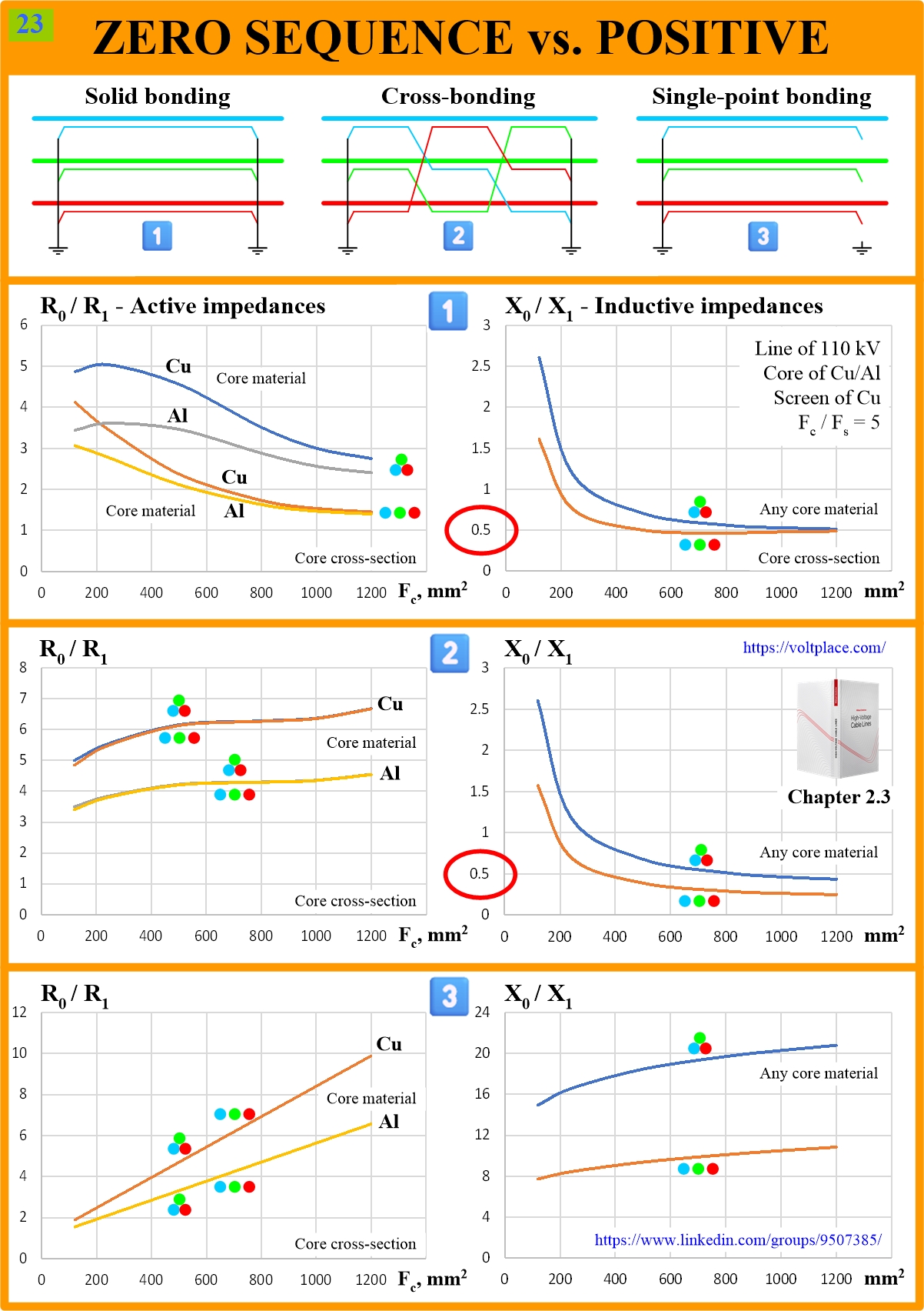
What are the ratios R0/R1 and X0/X1 of a cable line? Let us show this using an example of a 110 kV single-circuit line, which has no armor and along which there is no ECC. In calculations performed using simple and convenient formulas from the book, we will vary:
👉 screen bonding type (1️⃣-2️⃣-3️⃣);
👉 core cross section Fc and its material (Cu, Al);
👉 Cu-screen cross section Fs (based on the average estimate Fc/Fs=5);
👉 distance between the phases (trefoil or laying in a flat with the distance between the axes of adjacent phases equal to 0.2 m).
As can be seen from the graphs, the parameters of the zero sequence can differ significantly from the parameters of the positive. Of course, in calculating short-circuit currents, we are interested not only in R and X, but also in the overall impedance Z of the line. It can be shown that with core cross-sections of 500 mm2 and above, the active impedance of the cable line is usually several times less than its inductive impedance. Thus, for such lines, the main attention should be paid to X0/X1, and not to R0/R1.
For core cross-sections of 500 mm2 and above, for the most interesting options 1 and 2, typical for cable lines with a length of more than 500-1000 m, it can be seen that X0/X1<0.5. If we used X0/X1=1, as is often done (instead of X0/X1<0.5), then our calculations would give us single-phase short-circuit currents up to 20-30% less than they actually are in the cable network. Such a mistake in currents is dangerous!
You can discuss this post on LinkedIn, in the “High Voltage Cable Lines” group, by following the link to the post.