
Cable screen cross-bonding optimisation
Most HVAC cable lines with a length of more than 1 km have a cross-bonding of screens (for shorter lines, single-point bonding is used, with Earth Continuity Conductor or without it). When implementing a cross-bonding, the line must be divided into a multiple of three sections, and joints must be placed at the junction of the sections, from which the screens are output – their connection is performed in link boxes. Sometimes we can also find the non-separable cross-bonding shown in the photo, and it is not recommended to do so.
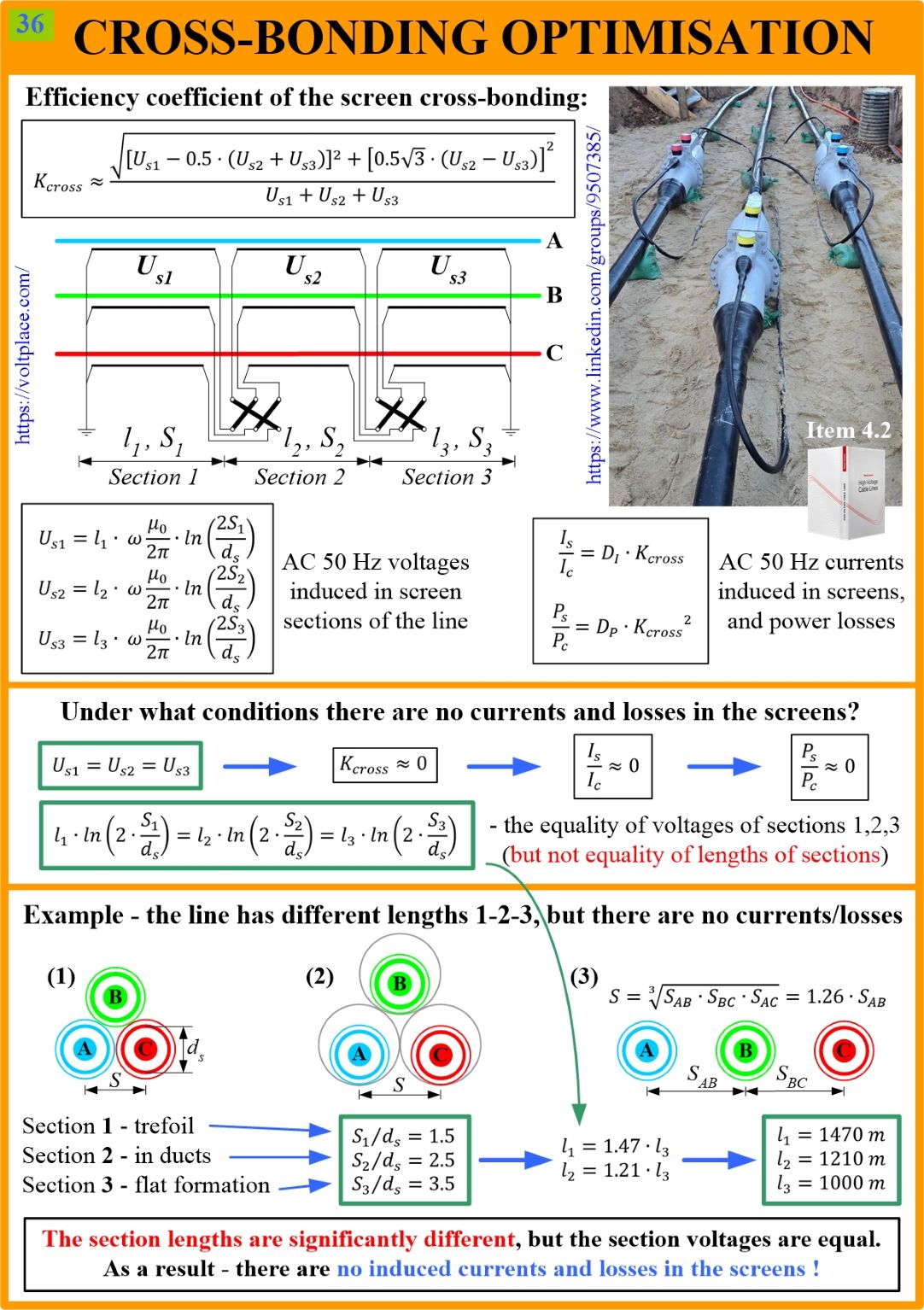
The design of a cross-bonding has a certain number of misconceptions, and one of them is that the lengths L1, L2, L3 of the sections they must be equal. Today’s post shows that this is not the case, and to achieve the effectiveness of cross-bonding, we must simultaneously look at the following factors:
✅ Ratio of lengths L1, L2, L3;
✅ Ratio of separation distances S1, S2, S3 between phases.
If the condition S1=S2=S3 is not fulfilled, it is useless to achieve equality L1=L2=L3. The difference in distances S1, S2, S3 can be compensated by the difference in lengths L1, L2, L3.
Most of cable lines have different ways of arranging cables along the line route, and they are characterised by different separation distance S:
➡️ trefoil (small S);
➡️ ducts (greater S);
➡️ flat formation (the greatest S).
For each of the sections L1, L2, L3 it is necessary to determine the average distances S1, S2, S3, considering the laying methods available along the section (trefoil, ducts, flat). Next, knowing L1, L2, L3 and S1, S2, S3, we need to calculate the 50 Hz voltages Us1, Us2, Us3 induced on the sections. To sum the three voltages, taking into account the angular shift between the vectors, it is convenient to use the coefficient of cross-bonding (Kcross).
Then we can look at the 50 Hz currents (Is) and losses (Ps) in the screens, or rather their values relative to the currents (Ic) and losses (Pc) in the cores. The absence of currents and losses in the screens, that is, the ideal cross-bonding, is achieved under the condition Us1=Us2=Us3, and not under L1=L2=L3.
As an example, let us say we have sections L1, L2, L3, and along each of them, the relative position is preserved – let it be trefoil (S1), ducts (S2), flat (S3). Knowing the screen’s diameter (ds), we will find the ratios S1/ds, S2/ds, S3/ds, after which we can easily determine at what ratio of lengths L1, L2, L3 we will achieve the ideal condition Us1=Us2=Us3.
In the example, it can be seen that to achieve an ideal cross-bonding, it is necessary to have L1=1.47*L3 and L2=1.21*L3, that is, the lengths of the longest and shortest sections differ by almost 1.5 times. Not L1=L2=L3 (!)
So, when designing a cross-bonding, the equality of section lengths does not guarantee that you will not have currents and losses in the screens. Please, always look at the combination of section lengths and laying methods.
You can discuss this post on LinkedIn, in the “High Voltage Cable Lines” group, by following the link to the post.