
Cable selection based on powerflow
We have good tools for thermal calculation of cables (IEC 60287), and we think we are getting accurate calculation results. Unfortunately, truly accurate results are only possible if we have accurate input data. Today, let’s give an example of why the normal mode current that customers give us is in some cases insufficient to correctly select the cable cross-section.
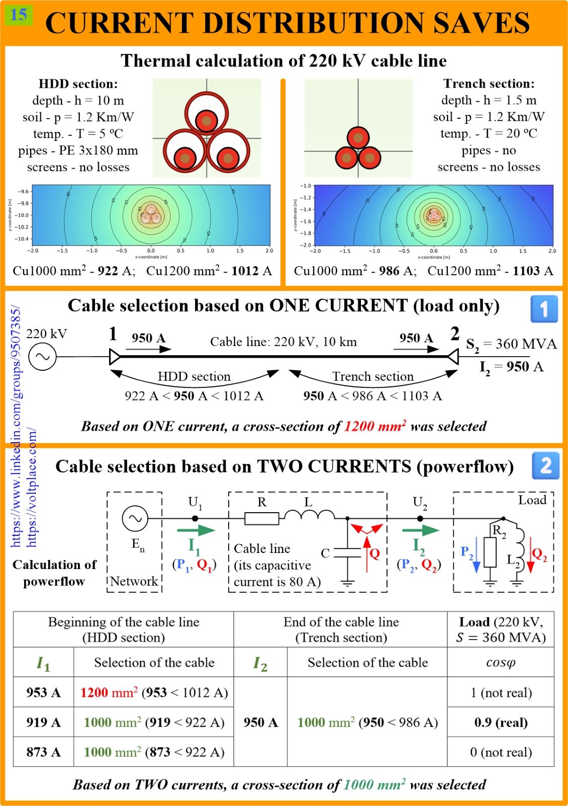
At the top of the slide, the results of the thermal calculation of a 220 kV cable line are shown, for sections laid using horizontal directional drilling (HDD) and trenches. Ampacity values are obtained for these two types of laying, with the help of Cableizer software according to IEC 60287, and everything is clear and precise. However, now let’s look on how these ampacities can be used when designing a real cable line. Suppose we have to build a 10 km long 220 kV cable line laid in a trench but with a HDD section at the beginning of the line. Let’s look at options 1️⃣ and 2️⃣ for selecting cables.
1️⃣ The customer gave us one current value of 950 A, calculating it based on the required load capacity (360 MVA). According to this current, we see:
🔹an HDD requires 1200 mm2;
🔹a trench requires 1000 mm2.
In order to have the same cross-section along the line, we choose 1200 mm2.
2️⃣ The customer, realizing that the line always generates reactive power (the capacitive current of a 220 kV 10 km long line is about 80 A), calculated the network normal operation mode and found current distribution along the line for us, the results of which are shown in the table. The reactive power (Q) generated by the capacitance of the cable line is consumed by both the network and the load. As a result, the load receives the reactive power it needs from the cable, rather than from the network. This leads to the fact that the current at the beginning of the line is dozens of amperes less than at the end of the line – this is shown in the table. It turns out:
🔹an HDD requires 1000 mm2 (not 1200 !!!);
🔹a trench requires 1000 mm2.
In order to have the same cross-section along the line, we choose 1000 mm2 (not 1200 !!!).
The reason for the difference in currents at the beginning (I1) and at the end (I2) is the reactive power generated by the line. The difference in currents depends on the following factors:
✅ voltage class, core cross-section and cable length (the differences between currents I1 and I2 are typical for 110-500 kV lines with a length of more than 5 km);
✅ the properties of the load, that is, the ratio of its active and reactive power (the differences between currents I1 and I2 are characteristic when the load needs not only active, but also reactive power, that is at power factor cosF<1).
So, when designing 110-500 kV cable lines with a length of more than 5 km, it is advantageous to know not only the load current, but the current distribution along the line. IEC 60827 is a good tool, but let’s think about what currents we use.